Everything seems to be working. However, the audio level is very low and muffled
I'm not sure if this is by design or if it's because I have made a mistake with a component value somewhere or if I have a bad firmware file
I will need to investigate further. I plugged it into an attenuator module (Mutable Veils) and the gain kicks it up
It does sound like the weird Oxygene/Equinoxe pattern generator but it's very lackluster. Sounds cool, kind of...
I paid $19 (USD)for the PCB/Panel set. If I had paid more I would have been very disappointed judging on the way it sounds right now.
Firmware Installation
I was successful with installing firmware on the Mini Pops ATMEGA328P IC using two different methods
Method #1 uses an AVRISP MKII Hardware Programmer and a Windows PC
Method #2 uses a Minipro TL866CS Hardware Programmer and a Windows PC. This method is easier but the hardware is more expensive
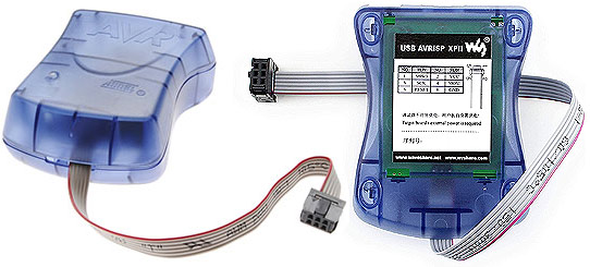
(AVRISP MKII Hardware Programmer)
Firmware Install Method #1
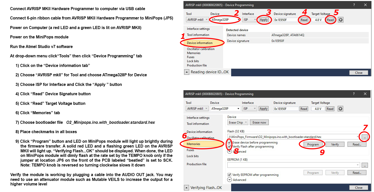
Using an AVRISP MKII Hardware Programmer and the free Atmel Studio v7 software for Windows
No extra adapter cables were needed... just the 6‑pin ribbon cable that's hard‑wired to the Programmer and the USB cable connected to the computer. Refer to the image below for detailed instructions on how to install the firmware. I used the firmware *.hex file named O2_Minipops.ino.with_bootloader.standard.hex
If needed: Download Atmel Studio v7 for Windows
Now that the firmware is installed, the module will be active at power up and the yellow TEMPO LED will blink at the set tempo rate (if you have the JP6 jumper set to SCK)
The TEMPO knob has a reversed action. Turning it clockwise slows the tempo down. Hmmm? Weird design
Firmware Install Method #2
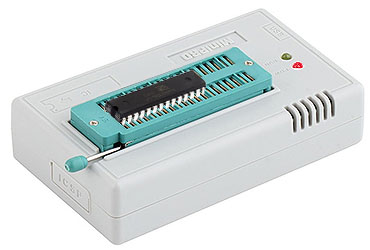
(Minipro TL866CS EPROM Burner)
(If you are new at this, I have created a webpage for beginners which describes how to use a TL866CS EPROM Burner here)
Run the TL866A/CS Application Software and follow these steps in order
- Place the ATMEGA328P IC in the TL866CS EPROM Burner (make absolutely sure sure the notch is facing the correct direction)
- From the drop‑down menu choose Select IC ▻ Search and Select
- In the Search Device textbox enter ATMEGA328P and press the Select button
- From the drop‑down menu choose File ▻ Open and choose the firmware *.hex file named O2_Minipops.ino.with_bootloader.standard.hex
- Place a dot inside the radio button for ☉ INTEL HEX and then press the OK button
- Place checkmarks in the boxes for
- ☑ Erase Before
- ☑ Verify After
- ☑ Check ID
- ☑ Set Range ALL
- From the drop‑down menu choose Device(D) ▻ Program(P)
- Place a checkmark inside all of the boxes and press the Program button
- If no errors are returned and the message "Programming Successful!" is displayed then the firmware was installed correctly
- Remove the ATMEGA328P IC from the TL866CS EPROM burner and install it in the Mini Pops PCB IC socket
The TEMPO knob has a reversed action. Turning it clockwise slows the tempo down. Hmmm? Weird design
Miscellaneous Install Notes
There are no build notes from the developer online anywhere, no schematics and no user manual so there are some mystery items on the PCB. I'm clueless about how these three items work
- SW11 (Back of PCB)
- This is an SMD microswitch. When pressed, the module ceases operation
- When released, the module starts up again. Perhaps a reset switch?
- The BOM says "Optional, not needed". Purpose unknown
- This is an SMD microswitch. When pressed, the module ceases operation
- JP2 (Back of PCB)
- The BOM says "Optional, not needed". Purpose unknown
- This is a 5-pin 2.54mm male header marked AMUX on top and GND A0 A1 A2 A3 A4 on bottom
- When I Google these pin labels, several references to "Arduino" and "Teensy" are the result. No doubt, something for installing firmware
- When I Google these pin labels, several references to "Arduino" and "Teensy" are the result. No doubt, something for installing firmware
- JP6 (Front of PCB) - This is a 3-pin 2.54mm male header marked beatled SCK/A3
- When a two-position jumper is placed across the SCK position, the TEMPO LED blinks dimly and matches up with the rate set by the TEMPO knob
- When a two-position jumper is placed across the A3 position, the TEMPO LED lights up solid during the last 4 beats of a 16-beat step
- The LED then turns off every time the RESET OUT jack sends a pulse and remains dark until the last 4 beats
- When a two-position jumper is placed across the SCK position, the TEMPO LED blinks dimly and matches up with the rate set by the TEMPO knob
The Information On This Page Is Current As Of