My Favorite Eurorack PCB/Panel DIY Builds And Mods
Remember... there's ALWAYS enough room for one more module in your rack! If not... buy another rack
| SLOTHS (NLC) | CVPAL (Mutated) | PLAITS (Mutated) | PØWR (VPME.DE) |
| BURST (Befaco) | SHELVES (Mutated) | WAVESLICER (Horstronic) | SPIN FV‑1 (mxmxmx) |
| LFOR (ST Modular) | TWO NINE FIVE (MMI) | HONEYEATER (ST Modular) | ELEMENTS (Mutated) |
| RAMPAGE (Befaco) | MINI POPS (Old Crow) | CHAQUO v2.0 (Elby Designs) | GRAINS (GinkoSynthese) |
| 4R (Transient Modules) | PURE NOISE (GMSN!) | SWITCHED RESISTOR (Barton) | JUPITER STORM (HexInverter) |
| 4046 SHAPER (Barton) | EUROBUFFER (Barton) | PLANCKS MK2 8HP (Jak Plugg) | CHAOTICA v1.1 (Elby Designs) |
| ANALOG DRUM (Barton) | CUSTOM RAM CARD (DoJoe) | QUAD DECAY A‑142‑4 (Doepfer) | EURO KASTLE v2 (ST Modular) |
| ZEROSCOPE (VPME.DE) | WAVE PULSE ANIMATOR (Barton) | CLOUDS w/KAMMERL (Mutated) | 4013 DUAL FLIP‑FLOP (Omiindustriies) |
| ÷N COM (Random*Source) | RADIO MUSIC (Music Thing Modular) | QUAD TRAPEZOIDAL LFO (Barton) | CGS10 KEYBOARD/TRANSPOSER (TAT) |
| TOGGLE ROUTER (Barton) | EP‑420 & CORE 420 (Pittsburgh Modular) | DISCRETE SV‑VCF (Manhattan Analog) | AUTO SEQUENCER (Barton) |
| QTFD (Barton) | µGrids (Mutated) |
Expander DIY
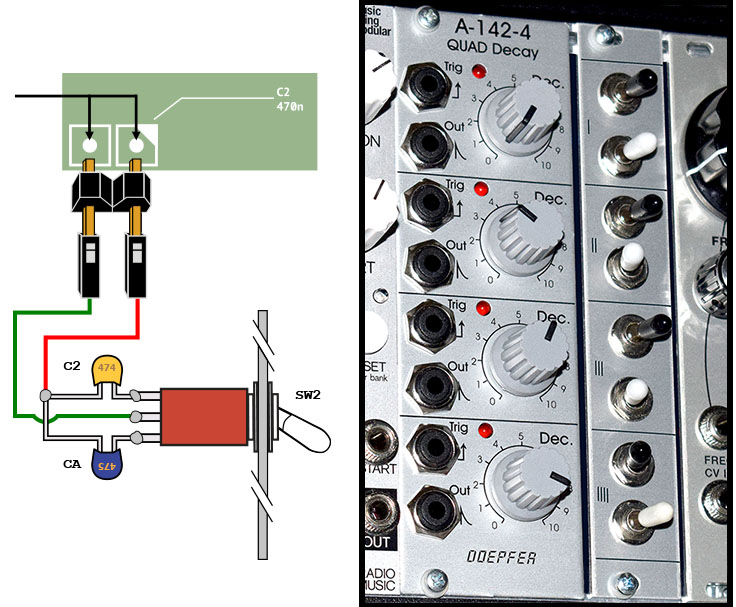
This low cost DIY adds eight toggle switches onto a separate 4HP panel which enables you to switch between self‑oscillating or trigger mode and/or time delay ranges of 2ms/2sec or 20ms/20sec. This add‑on increases the flexibility of this already versatile module
 A‑142‑4 Quad Decay Expander DIY (PDF)
Review + Free Sample Pack Downloads
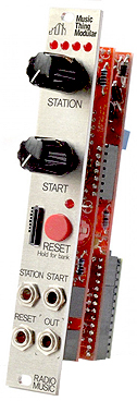
- Bad News: Sadly, the Teensy v3.2 board (a key component for building this module) has been discontinued and is out of stock everywhere. Those who built a Radio Music, Chord Organ or Sound Study AirWAV (a Radio Music clone) prior to 2020 and those who can find a used one are extremely lucky. There was a brief production run of brand new 3.2 modules in October 2023 but these have since sold out
and officially signify the end of Teensy 3.2 production
This module is an easy build because all of the components are through‑hole. It is EXTREMELY cost effective when sourcing your own parts from mouser.com. As a bonus, new firmware now enables you to turn the Radio Music module into a completely different module... the Chord Organ. Instead of playing samples from the MicroSD card, it synthesizes chords
Build Issues
- 1) Radio Music v2.x PCB's and all AirWAV PCB's have an issue with distorted sound after the module has been powered on for a while. An easy fix is to attach a 100KΩ resistor between two solder points on back of the Logic PCB (in between the leads of C4). I used a 1206 case size SMD resistor (see image here) but a regular through‑hole resistor with bent leads will also work. The distortion issue is documented at this link on the Music Thing Modular support webpage
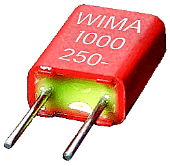
- 2) If you have built an AirWAV module, the BOM (dated Oct 4, 2016) has the wrong capacitor types listed for C2 and C3. These should be 100nf Poly Box capacitors but instead they are shown on the BOM as Ceramic capacitors. So... why is this important? Ceramic capacitors tend to behave as microphones and in an audio circuit they will pick up unwanted ambient sounds and voltage crosstalk. C2 and C3 are part of the main Audio Out circuit while most of the other capacitors are connected to ground and used as bypass filters or for decoupling. The original Music Thing Modular BOM is at this link and clearly shows that C2 and C3 should be Poly Box capacitors, not ceramic
- 3) I've built more than ten Radio Music modules and 99.9% of the time when I encountered a problem, it always turned out to be an issue with the microSD card. If you encounter any problems, I suggest checking these things on the micro SD card first
- Ensure the number of folders and sample files do not exceed the maximum limits and the proper name format is used
- 8+3 naming convention [ 12345678.WAV or 12345678.RAW ]
- 1,200 file limit [ 16 folders x 75 files per folder ]
 Exceeding any of these limits will cause the module to freeze and lock‑up
- Check the settings.txt configuration file. Some combinations will collide with each other and prevent playback
- Only use a quality name brand microSD card like SanDisk, Kingston or Kodak. Some generic brands keep the module from booting
- When all else fails, backup all 16 folders + the settings.txt file, reformat and then copy everything back onto the microSD card
- Ensure the number of folders and sample files do not exceed the maximum limits and the proper name format is used
If you are looking for some very weird and strange sample packs for your Radio Music module, there are more than 16GB of free samples w/CheatSheets at these links:
- NOTE: These samples were created way, way back in 2015 when the initial firmware required headerless *.RAW format files. If you are using a settings.txt file on the microSD card with newer firmware, ensure that pitchMode=0 or else these samples will playback at an extremely slow speed... about 5x slower
Radio Music Weird Samples #1 (Fits on an 8GB MicroSD card)
Radio Music Weird Samples #2 (Fits on a 4GB MicroSD card)
Radio Music Weird Samples #3 (Fits on a 4GB MicroSD card)
Radio Music Weird Samples #4 (Fits on a 1GB MicroSD card)
Illuminated RESET Switch Mod
This is kind of a worthless and time consuming mod but I like the way it looks. There are four C&K illuminated switches available which have an LED inside. It can replace the regular RESET switch listed on the BOM. It looks great when you press it or when a RESET or STATION signal is sent to the module via those two CV jacks. There are two extra pins on the switch that need to be bent at a 90 degree angle, have jumper wires added and soldered onto the PCB. The positive LED lead of the new switch is wired to the positive lead of the existing activity LED and the negative LED lead is wired to any available ground node (see Figure H). Part numbers for the four illuminated switches are:
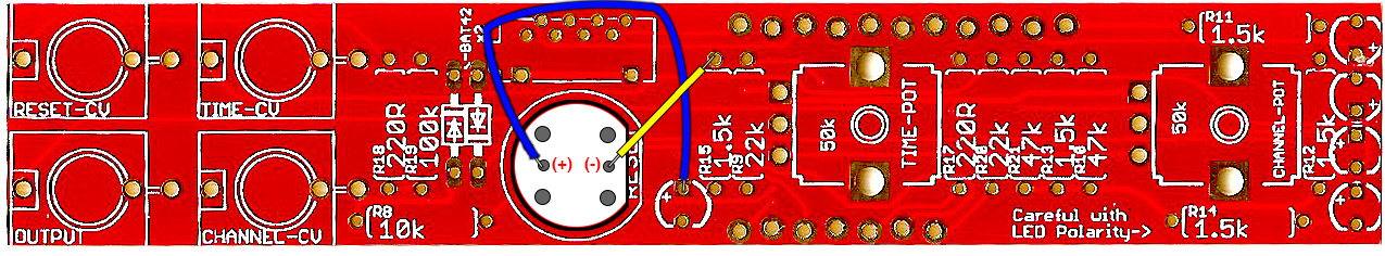
(Figure H: Click For Larger Image)
          Blue: D6RLBUF1 LFS        Green: D6RLGNF1 LFS
           Red: D6RLRDF1 LFS        White: D6RLWHF1 LFS
Here is a video of the blue switch in action
Illuminated Radio Music RESET Switch (YouTube Link)
 UPDATE AUGUST 2021
- A few users are reporting that with some Eurorack cases, Radio Music and Chord Organ will only power on about 50% of the time
- Solution #1: Reflow new solder for the two 10µF Electrolytic Capacitors at silkscreen locations C6 and C7
- This worked for me. I turned my soldering iron temperature higher than normal, used a heatsink and reflowed new solder
- Solution #2: Using a low quality generic microSD card will sometimes prevent the module from powering on
- Use a high quality brand name microSD such as SanDisk or Kingston
- Solution #3: Remove the microSD card before powering on. After powering on, plug the microSD card back in for normal operation
- This is only a temporary fix but prior to discovering Solution #1, I used this method all the time
- Solution #4: There is no Solution #4. Some Eurorack case power supplies just won't play nice with this module
- Solution #1: Reflow new solder for the two 10µF Electrolytic Capacitors at silkscreen locations C6 and C7
 Pothole Hotline Music has an interesting YouTube tutorial using envelopes, filters and dynamics to control Radio Music
Panel/PCB Build Notes & Review
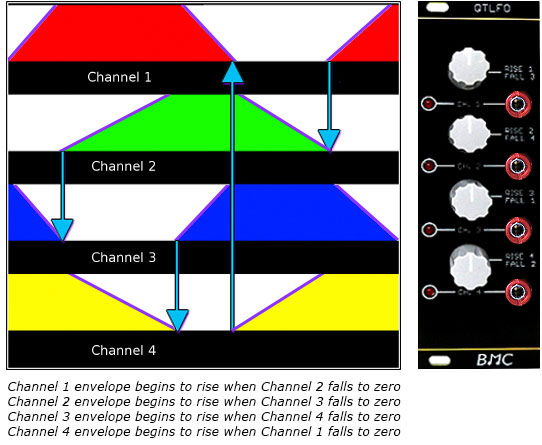
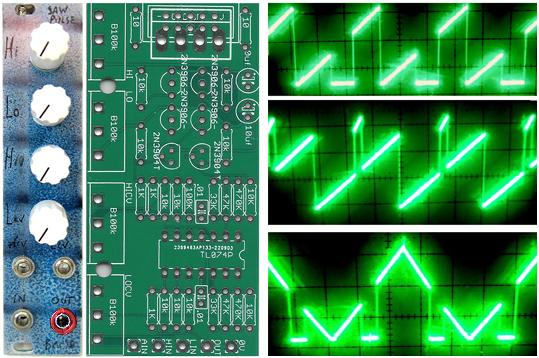
Over time, this module turned out to be my #1 favorite BMC circuit. Since 2015, the designer has updated and fine tuned this circuit and now it works better than ever. The QTLFO is a very interesting module the way it feeds itself different envelope timing sequences. It's not what one would typically call a "random" setting but it certainly adds unpredictable patterns into the mix. It sends four trapezoidal CV outputs which are synchronized with each other. One output begins to rise when the previous output falls and reaches zero. After the fourth output reaches zero, the entire sequence cycles again and again. Each output has a separate knob to control rise and fall times. One use for this module could be to create some unique stereo (and even pseudo‑quadraphonic!) sound separation. I like to patch an output signal to the HARMONY CV Input on a Mutable Instrument PLAITS module. Mesmerizing Results!
This module is a very low‑cost, low‑count component build. The components used are very common and excluding the PCB/Panel, the cost was less than $9(USD) when ordering from Tayda Electronics. The most expensive components are the four anti‑log potentiometers at 50¢ each! The build was very easy and assembly time is minimal. I have compiled some easy order BOM lists for Mouser and Tayda "Quick Order" webpages for a v2.0 PCB build
QTLFO "Easy Order" BOM's
The newest v2.0 PCB and raw panel is always at Barton Musical Circuits and a high quality Oscillosaurus Panel is at ModularAddict.com
- Notes:
- 1) If you built this module using a v1.0 or v1.1 PCB, the new v2.0 PCB was released July 2023 which improves timing/stability +plus+ provides symmetrical rise and fall rates. A revised BOM and Build Guide is available here
- 2) With a suggestion from Michael Barton for my v2.0 build, I replaced both 2.2K resistors with 10K. This solved an issue I was having with the circuit freezing and LED#2 + LED#3 always remaining on
Panel/PCB Build Notes & Review
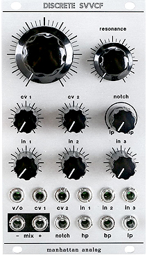
This module is similar to Oberheim's SEM filter and the mixer is inspired by Moog's CP3 module... also built with transistors which gives it a distinct sound. Although this is a labor intensive build, the end results are worth all of your efforts. My best advice for this build is to take a little time and do some research before you start building. If you focus too much on some of the earlier posts for the build discussions at modwiggler.com, you will be thoroughly confused because they deal with several different PCB versions. I definitely got lost because of "too many" suggestions. I found only a few posts which were actually relevant for my build (v1.4/Main Board + v1.3/Jack Board)
- I used Tayda Electronics 16mm pots with solder lugs as suggested by one Mod Wiggler. Big huge mistake. I was trying to save $$$ by using what I had in my parts kit. The amount of extra time I spent soldering these using solid wire was a giant hassle. Be sure to use right angle PCB mount pots which look like this (they are the same price as pots with solder lugs and will save you an enormous amount of assembly time so... it's a no‑brainer)
- Right Angle PCB Pots
- [1] B10K (Frequency) Tayda SKU: A-1624
- [3] B100K - (CV1/CV2/Notch) Tayda SKU: A-1628
- [1] B10K Dual Gang (Resonance) Tayda SKU: A-1997
- [3] A25K (IN1/IN2/IN3) Unfortunately, Tayda Electronics does not stock any of the A25K Audio/Log right angle variety so you will need to source these three potentiometers elsewhere
- Right Angle PCB Pots
- As suggested by the designer, I opted to use a 1K Tempco resistor at PCB silkscreen location R44*. This special resistor is available from Modular Addict. From what I've read about this, after being powered up for 2+ hours in the case, components tend to heat up and this Tempco is there to prevent temperature drift for that part of the circuit
- I was unable to find a BOM or build docs at the Manhattan Analog website but I did find a good BOM at this link for reference. There is also a Mouser Cart BOM at the Mod Wiggler link above but use that one with caution! Some of the transistors and other parts listed there are quite expensive. The BOM total $$$ was much higher than the parts I was able to source from Modular Addict and Tayda Electronics. With the exception of the Styrene Caps (P/N: 23PS210), Ferrite Beads (P/N: BL01RN1A1F1J) and the LM377 (P/N: LM337LZ/NOPB), I was able to source all components from Modular Addict and Tayda Electronics
- There are 13 SMD components. Two on the Main Board and eleven on the Jack Board. For the PCB versions listed above, the components are placed as follows:
- Jack Board (Back)
- (2) 0.1uf Caps @ Pad Locations Marked ".1"
- (2) 22pF Caps @ Pad Locations Marked "C"
- (2) 330R Resistor @ Pad Locations Marked "3"
- (4) 47K Resistor @ Pad Locations Marked "4"
- (1) TL072CDR IC @ Pad Location Marked "072"
- Main Board (Back)
- (2) 0.1uf Caps
Note that if you use a 1K resistor on the front of this board at PCB silkscreen location R44*, there will be two pairs of SMT pads which are not used and left unpopulated. One pair of pads is used for a 1K SMD mounted resistor (I used a Tempco through hole resistor on the front instead) and the the other pair of pads have large holes in them and are used only as test points. Compared to these test pads, the pads I populated with the 0.1uf capacitors have very, very small holes drilled in them. Much smaller than the test pads. I don't like working with SMD stuff but found all of these components were very easy to solder by hand using a fine tip iron
- Jack Board (Back)
- Some of the BOM's floating around are showing expensive bipolar transistors. The designer pretty much says not to bother using expensive transistors. Standard 2N3904 and 2N3906 transistors will work just fine. Quote from the designer - "I couldn't justify $6 for 4 transistors - x4 per board - when 2N390x at 2¢ each work and sound just as nice. As far as matching goes, I've built them with matched and unmatched transistors and couldn't really tell any difference. I recommend loosely matching them as a matter of best practice but it's not something you should worry about."
- I socketed the resistor at PCB silkscreen location R13* on the Main Board. The designer mentions this value can be experimented with to fine tune the mixer/filter sections. I am currently using a 330K resistor here (the default value is 390K) and it sounds great. As another builder mentioned, this 330K value slightly tames the resonance. I will experiment with other values later on. Suggested values to tinker with here are between 270K and 470K
https://www.modwiggler.com/forum/
Search for the phrase "Holy crap, this isn't hard"
I'm really digging this module. I built two and am happy to report these make a good substitution for the Oberheim synth sound I've always craved but never owned. Here are some links with a good collection of demos:
This video demonstrates a very cool effect similar to a track titled "905" on The Who's LP "Who Are You?". That track was played on one of the first multiphonic Polymoog synths way back in 1978. Another synth I've heard which comes close to this great effect is the Roland Super JX‑10/MKS‑70 - Patch G‑3: ROBODROID DELUXE 39 47
https://youtu.be/0ijh0IhOhOQ?t=2m28s
A very detailed overview and demo by DivKid
https://www.youtube.com/watch?v=IKi3_4VuUsg
A collection of audio demo clips. Check out "Bendy Bandpass"... oh yeah!
https://matttechmodulardemos.bandcamp.com/album/manhattan-analog-svvcf
The PCB/Panel set is usually out of stock everywhere but you can still buy a PCB/Panel set (or a fully assembled module) direct from the designer at manhattananalog.com
Panel/PCB Build Notes & Review
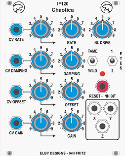
Thanks to this module, my life is Total Chaos! Of all the modules I own, Chaotica instantly moved to the #3 spot on my "Top 10 Module List" after building and hearing it. A phenomenal CV generator for complete mayhem!
The one major drawback you need to be aware of is that if you purchase an older version v1.1 PCB, it will not fit in a majority of enclosed racks. The PCB is incredibly deep at a whopping 101mm (4 inches). The newer v2.0 PCB modules have been redesigned at only 60mm deep and will and fit in most enclosed racks. To accommodate the depth, I had to build my own open‑back case. Other than this major flaw on the older versions, this one is a Highly Recommended Build!
- My full kit had eight PCB's to assemble. Yes... that's not a misprint. EIGHT. There is one large square main PCB. Mine was labeled as ED120 v1.1. Three of the rectangular PCB's are used for a majority of the pots and jacks. The other four PCB's are very small and are used to attach the Y, Z and RESET/INHIBIT Jacks and also the EYES Switch. I was a little confused about the four small PCB's because three were blue and labeled "Carrier" and one was green and labeled "Carrier V1.2". I sent an eMail to Elby Designs and was told that the solitary green one labeled "Carrier V1.2" is used for the EYES Switch. The A5K Pot is installed on the Main PCB at silkscreen location P101 (Labeled NL DRIVE on the front panel)
This is how I populated my PCB's with components
- Board Revision(PCB Type): Components(Silkscreen Location)
- ED120 v1.1(Main PCB): A5K Pot(P101), X Jack(J103) and TAME/WILD Switch (S101)
- Carrier(Small Blue PCB): Y(J102), Z(J101) and RESET/INHIBIT(J204) Jack
- Carrier V1.2(Small Green PCB): EYES Switch(S102)
- Panther - Jack-Switch Board Rev 3.1 (Rectangular PCB): Blue Jacks - CV RATE(J1), CV DAMPING(J2), CV OFFSET(J3) & CV GAIN(J4)
- Panther - Pot-Carrier Board Rev 1.4 (Rectangular PCB): A100K Log Pots - RATE(P1), DAMPING(P2), OFFSET(P3) & GAIN(P4)
- Panther - Pot-Carrier Board Rev 1.5 (Rectangular PCB): B100K Linear Pots (P1, P2, P3 & P4 - Attenuators labeled w/Right Arrow ⟶)
- Connections for the 16‑pin ribbon cables
- J201 on Main PCB ➟ ➟ J6 on Pot‑Carrier Board Rev 1.4 (Note: Don't confuse this with J6 on Pot‑Carrier Board Rev 1.5)
- J202 on Main PCB ➟ ➟ J6 on Pot‑Carrier Board Rev 1.5 (Note: Don't confuse this with J6 on Pot‑Carrier Board Rev 1.4)
- J203 on Main PCB ➟ ➟ J5 on Jack‑Switch Board Rev 3.1
- J301 on Main PCB ➟ ➟ Case Power
- If you have PCB revisions different from the ones I've presented here, I recommend that you eMail Elby Designs to get additional info for correct component placement. Elby Designs was friendly and also very fast to respond with technical help
- One of the best descriptions about this module and how it works is at Ian Fritz's website, the Chaotica designer. There are many audio clips here and also an in‑depth video
This module is somewhat difficult to purchase online. The full kit is always in stock at elby‑designs.com but these days, it's a little expensive to ship from Australia to the U.S.A. and elsewhere. Modular Addict used to keep this one in stock on a regular basis but I've not seen it around since early 2019
Panel/PCB Build Notes & Review
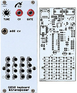
I find this to be a very useful module for my music style (Tangerine Dream, Vangelis, Ambient, etc...). Using the CV Out Jack and pressing buttons on the front panel during active sequences will transpose the riff up or down in a 16‑semitone range (one octave plus four‑semitones). This module also doubles as a keyboard which enables the operator to play one note at a time... great for sending triggers or percussive notes on the fly
This is a very easy build with a low cost, low parts count. It has a combination of through‑hole and SMD parts, all of which are easy to solder in place because everything is spread out on the PCB. The only part I had trouble finding was the specialty Matrix Keyboard Scanner IC made by Fairchild - P/N: 74C922. This IC is available at Jameco Electronics but it is pricey at $11. This specialty IC is also available at Amazon and eBay in quantity at a lower cost. This IC is no longer made by Fairchild which is why it's so expensive these days. There are 16 Tact Switches required. I used 6mm x 6mm x 13mm tact switches available from Tayda Electronics (SKU: A‑5156). I also purchased the Jacks (SKU: A‑2563) and Potentiometer (SKU: A‑1851) from Tayda Electronics. I was able to source the remaining components from mouser.com. When you buy the PCB/Panel, a Xerox page is included with a Build Guide and BOM. Calibration was a breeze with the supplied instructions
- I'm always curious about unused pads on DIY builds. I contacted the designer of this one and he explained the following about the unused pads as detailed in this image
- The two unmarked pads on the front are for a bypass capacitor (100 nF) which isn't really necessary
- The two pads with holes marked CV and Gate are for possible use if one wants to build the keyboard into some other device, say a real keyboard or some other keypad thing, like an old telephone pad or something else
I've put together a Mouser Cart BOM and also a detailed BOM in PDF format for downloading here
Mouser Cart *
BOM (PDF)
* SPECIAL NOTE: The Mouser Cart does not contain all required parts for this build. Refer to the BOM PDF for Jack, Tact Switch, 74C922 IC & Potentiometer part numbers available from Tayda Electronics. The BOM PDF has a link to jameco.com where I purchased the 74C922 Matrix Keyboard Scanner IC. As always, when purchasing parts from Mouser, increase the quantities of resistors and capacitors to 10 or 100 for substantial savings
Some of the pitfalls you will need to watch out for when building this one are:
- Make sure you install all of the tall components on the back of the PCB
- These components are the two Trimmers, the Power Header and the electrolytic capacitors if you use part numbers other than ones shown on the BOM (i.e. taller than 9mm. Silkscreen outlines on the front of the PCB are misleading. If you install these tall components on the front, you won't be able to fit the front panel in place. You might be able to bend taller electrolytic capacitors downward at a 90 degree angle to make them fit but the two trimmers and power header will absolutely need to be installed on the back. For my build, I used two of these capacitors (Panasonic P/N: EEA-GA1H100) and one of these (Panasonic P/N: ECE-A1HKA2R2I)
- These components are the two Trimmers, the Power Header and the electrolytic capacitors if you use part numbers other than ones shown on the BOM (i.e. taller than 9mm. Silkscreen outlines on the front of the PCB are misleading. If you install these tall components on the front, you won't be able to fit the front panel in place. You might be able to bend taller electrolytic capacitors downward at a 90 degree angle to make them fit but the two trimmers and power header will absolutely need to be installed on the back. For my build, I used two of these capacitors (Panasonic P/N: EEA-GA1H100) and one of these (Panasonic P/N: ECE-A1HKA2R2I)
- The standoffs and nuts I used to connect the front panel to the PCB were made of nylon. This is recommended in order to prevent any short‑circuits on the PCB close to where some of the tact switch pins are located. If you decide to use metal standoffs and metal nuts instead, use some plastic washers to raise the standoffs up & away from the PCB
- There is a Xerox page included with each PCB/Panel kit. There are some misprints with the BOM quantities
- Only four 200K resistors are shown but you will actually need five 200K resistors
- Only nine 100K resistors are shown but you will actually need ten 100K resistors
As of October 2022, the PCB/Panel kits have long sold out. However, built modules show up from time to time at eBay and reverb.com
Panel/PCB Build Notes & Review
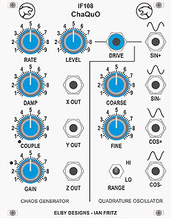
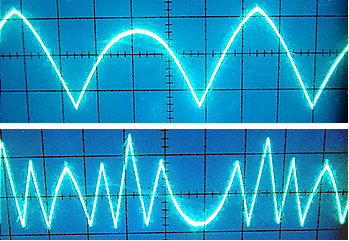
This chaos generator is similar to Chaotica. I like Chaotica better than ChaQuO because there are more CV inputs which can make things extremely wild at times. ChaQuO is slightly different because it has a separate Quadrature Oscillator with extra outputs for Sin+ / Sin- / Cos+ / Cos- and these four signals can be used to supply a drive signal for the chaos generator section. The designer, Ian Fritz, sums up differences between the Chaotica and ChaQuO modules;
- "Chaos requires three degrees of freedom, or variables. Chaotica has three VC OpAmp integrators that correspond to the three degrees of freedom, so it can oscillate on its own. ChaQuO is a second order system, and an external driving source is required to provide the third degree of freedom. The double‑well chaos (EZ Chaos) board was the first board I designed, and it was intended to be the simplest way for folks to get into a DIY chaos generator. ChaQuO with its built‑in driving source was its follow‑on."
Thankfully, the new ChaQuO v2.0 PCB does not have the same issue as the v1.x Chaotica design... an extremely deep PCB. This one fits nicely into most cases and is only 55mm deep (compared to Chaotica which is 101mm). The clever design now being used on Elby v2.0 builds was somewhat tricky for me to figure out at first. Once I looked at all the documentation and the 3D PDF files, it started to make sense. There were no images of a completed module in the Build Guides anywhere so I've put together some notes and images which might make this build a little easier to complete
- There is a jumper wire which needs to be soldered onto the Main PCB which runs from the Column 2 PCB 16‑pin header over to the Column 3 PCB 20‑pin header. The easiest way is to run this across the top of the PCB (Figure A and B)
- Take care when plugging the Main PCB into the four rectangular PCB's. The 16‑pin and 20‑pin headers need to be aligned in the center. It's quite easy to accidentally shift these pin headers left or right and plug the Main PCB board off‑center. The male headers have notches but the female headers do not. Luckily, I discovered my mistake before I turned on the power (Figure C)
- Before soldering the 16‑pin and 20‑pin headers in place on the Main PCB, assemble all of the PCB's in their correct positions, plug in all of the PCB's into their headers and then solder the pin headers in place on the Main PCB. This will ensure a better fit during the final assembly
- There are ten PCB's in this kit! Not a misprint. TEN! Lining up the four rectangular PCB's in the correct order is crucial. Refer to the image for the correct order (Figure D)
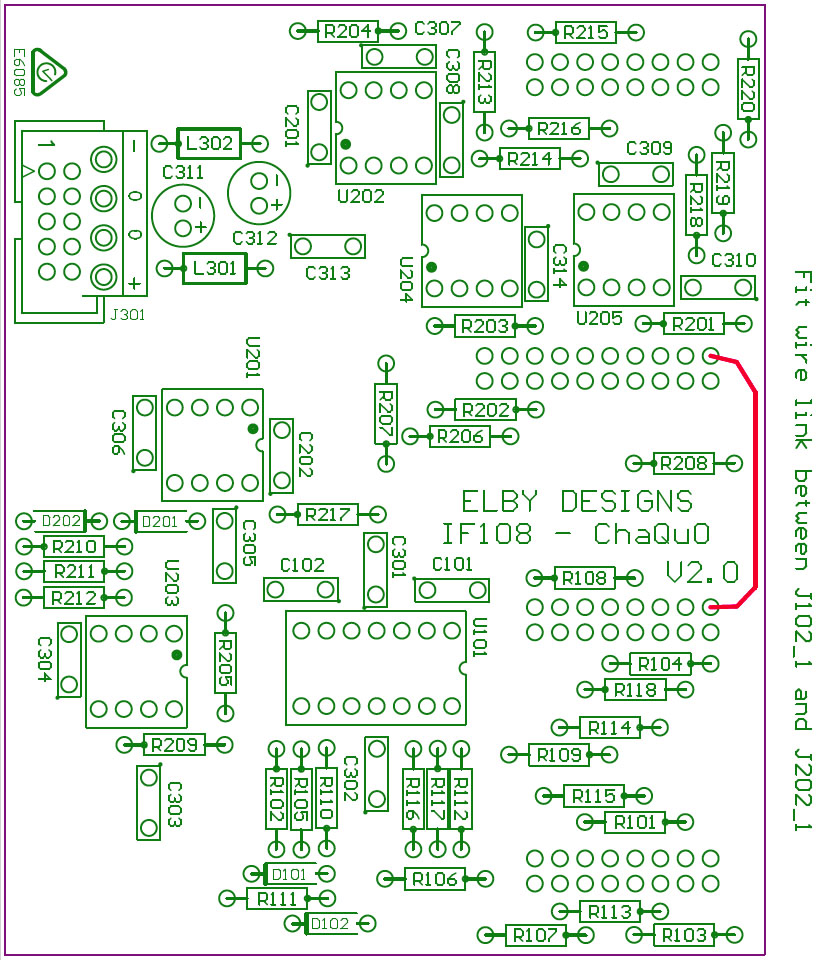
Figure A (Click For Larger Image) |

Figure B (Click For Larger Image) |
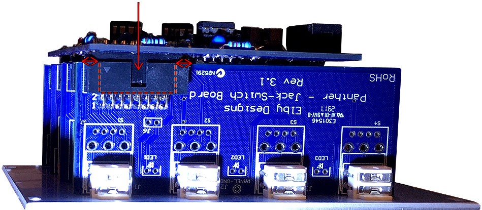
Figure C (Click For Larger Image) |
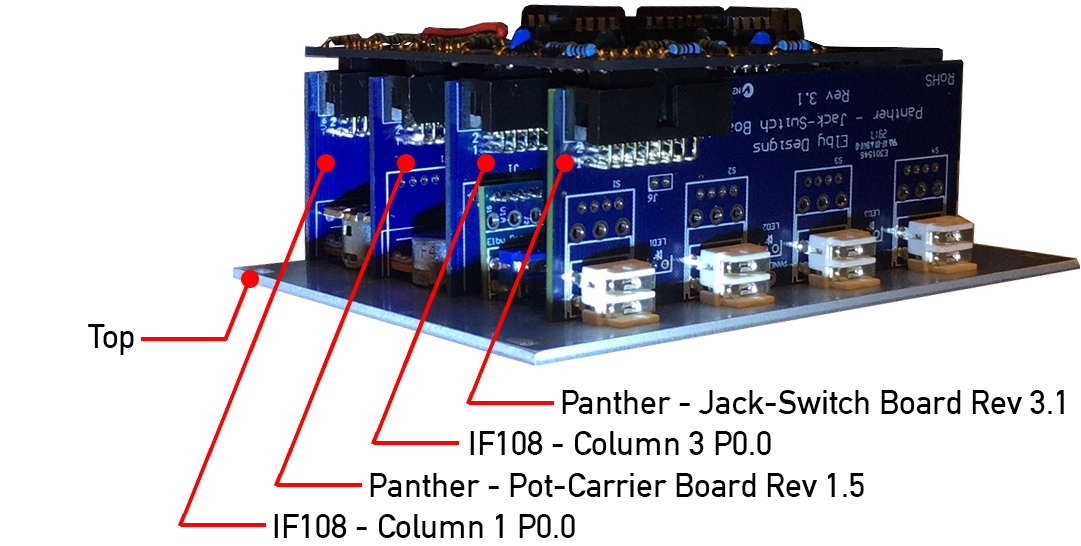
Figure D (Click For Larger Image) |
Panel/PCB Build Notes & Review
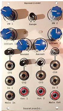
I was absolutely blown away by all of the amazing sounds I'm getting out of this module!
Three IN's, four CV IN's, three OUT's and eleven knobs enable a large array of different "Waveslicing" audio options
A Highly Recommended Build for many reasons:
- The creator really put some thought into the design of this PCB layout. He had the DIY people in mind. There are solder pads on my v2.3 PCB which are double duty... resistors can be either SMD or mounted through hole. I wish more designers would offer this as an option
- Likewise, the 3.5mm mounting holes are versatile because they will accept either PJ301BM or PJ398SM jacks. Very cool when searching your inventory for available parts!
- The overall DIY cost was very low because of all the easy to find parts. With the exception of the LM4040, I was able to find everything at Tayda Electronics. I hate builds which use SMD but this one was quite easy because none of the IC's are SMD. They're all through‑hole. There are 24 SMD components (all capacitors)... but don't let that prevent you from getting this PCB/Panel. It was a very easy build and it sounds great
The PCB/Panel set is out of stock everywhere but fully built modules at a good price will show up on eBay and reverb.com from time to time
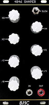
Panel/PCB Build Notes & Review
I was able to easily source all the components from Tayda Electronics at a minimal cost of only $8 for everything. The PCB is extremely well made and easy to solder. The build guide is easy to follow and there are no surprises. As usual, the panel made by Oscillosaurus looks fantastic
The things I would have changed with my build is to add sockets for the 1uF and 10uF electrolytic caps (Slew Control) and also for the 10K resistor. The build guide mentions that you can substitute different values at the 10K resistor location and I think it would also be interesting to alter the two electrolytic caps for experimentation
I wish I had discovered the Barton DIY PCB's and Panels a long time ago. Barton DIY modules are some incredible value priced gadgets and the 4046 Waveshaper is no exception. The demo video made by Barton is OK but... I encourage you to watch this one made by MidiverseTV instead. It gets into some better sound details and shows the output on an oscilloscope
https://www.youtube.com/watch?v=WcAFAW3IVic
The PCB is always at Barton Musical Circuits and the PCB/Panel set shows up in‑stock from time to time at ModularAddict.com
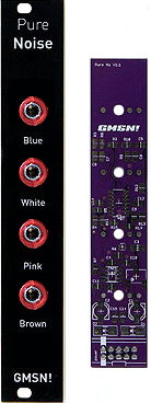
Panel/PCB Build Notes & Review
This one is a great value‑priced, multi‑NOISE module with less than 45 components
The four different noise sources (Blue, White, Pink & Brown) are quite interesting when used with a Sample & Hold module. They each produce unique random glitches. For years, I've been using the PGH Toolbox module to generate noise. It's nice to have these four different noise sources for a wider variety of randomness. Some of these noise sources are MUCH brighter than the solitary PGH Toolbox noise source
- Except for the DMMT3904W 6‑pin Matched Bipolar Transistor in a !!!Microscopic!!! SOT‑363 package, all of the SMT parts were very easy to solder in place. As stated by the module designer in his calibration video, not all DMMT3904W IC's will work because the modern day tolerances of these IC's are "too precise". In a batch of ten, maybe eight will work correctly with his design. After building, you may need to remove the DMMT3904W and try another one if no noise is generated. My first build did not work. Lucky me! After replacing the DMMT3904W with another one from the same batch, it worked perfectly. I'm glad I watched the designer's calibration video first. So... moral of the story... buy ten DMMT3904W IC's in case you need to replace one. They're inexpensive
- There is a helpful trimmer calibration video on YouTube here
- EagleCAD Schematics and Board files are here
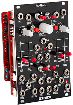
Panel/PCB Build Notes & Review
With more than 800+ solder connections and 300+ components, the Rampage PCB/Panel is a VERY labor intensive build. However, the payoff is totally worth the effort. The number of new features this single module can add to your rack is staggering... Burst Generator, Polyrhythmic Gate Generator, Ping‑Pong LFO, Dual Low Pass Filter, Voltage Controlled Trigger Delay, Peak Voltage Follower and Dual Slope Detector... just to name a few
I've built more than 25+ different PCB/Panel kits but the Rampage is my first BEFACO project. I was really impressed with the quality double sided PCB's and the accurate/easy to follow assembly guide and BOM. Everything worked the first time when I powered‑up and I'm looking forward to building more BEFACO modules
If you plan to source components yourself such as mini‑toggle switches, resistors, pots and LED's... be aware of the following for PCB v1.3.2 (and other PCB versions)
- Standard mini‑toggle switches from Tayda Electronics and eBay will NOT work because the through‑hole lugs are too wide for the PCB. Use the exact part number as shown in the BOM
- Likewise, standard pots from Tayda Electronics will not work because BEFACO pots have a unique footprint and some are the dual‑gang variety with six "through‑hole" solder pins. These special pots are sometimes stocked at the modularaddict.com PARTS webpage
- Resistor spaces on the PCB's are designed for use with smaller 1/8W resistors having a body length of 3.25mm. I always use 1/4W resistors for my builds because I currently have a bazillion of these in my parts inventory. I populated the entire board with the larger 1/4W variety instead which have a body length of 6mm. They worked but I had to insert each one at a 45 degree angle which led to spacing problems while trying to sandwich the two PCB's together. Using longer header socket pins solved this issue
- If you plan on using IC sockets, be aware that there is virtually no clearance between the two circuit boards. I had to use some longer than normal header socket pins when joining the two PCB's together. If you plan to solder the IC's directly onto the PCB instead, this is a non‑issue
- Because of the low clearance between PCB's, you may need to mount the two electrolytic caps horizontally if they are not the "low profile" variety
- The BOM calls for 2mm LED's. I only keep 3mm LED's in my inventory. Although these are too big to fit completely into the front panel holes, they still worked when recessed. However, there is a slight bleed‑through to adjacent LED's when they are lit. I opted not to purchase the 2mm variety LED's because they are priced 10x higher than more commonly found 3mm LED's. If you are picky about LED bleed‑through, you may want to source expensive 2mm LED's instead
Currently out of stock at most places but the PCB/Panel Set and the Full Kit show up sometimes at ModularAddict.com

Panel/PCB Build Notes & Review
I'm crazy about this pØwr utility module from vpme.de. I think every Eurorack DIY'er needs one of these. This is very convenient when testing and calibrating new builds. Sure... you could have a ribbon cable sticking out the side of your rack instead but this module looks classy *PLUS* safety‑wise, the mini‑toggle switch keeps the 16‑pin header connector powered off when you're not using it
This is a super easy build, a low‑cost PCB/Panel and requires less than $2 in parts!!! The oddball connector sandwiched in the middle was supplied with my panel. As mentioned in the build thread at Mod Wiggler, some inexpensive mini‑toggle switches with solder lugs are too big. For my inexpensive mini‑toggle switch, I had to use a Dremel tool and carefully file down the solder lugs and some red plastic before the oddball connector would mate flush with both panels. I would recommend buying the correct sized mini‑toggle switch with PCB pins to avoid the hassle. This module has been working overtime in my rack lately. Incredibly useful!!!
As of February 2023 The PCB/Panel set is at ModularAddict.com
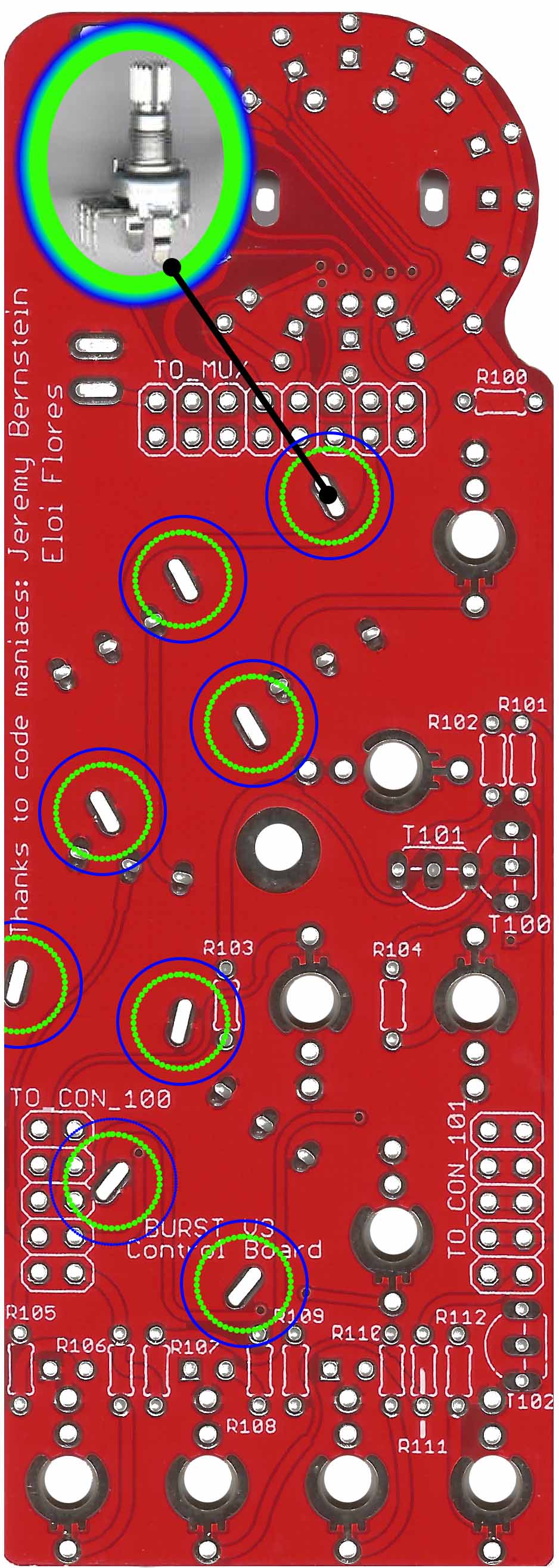
Kit Build Notes & Review
Another Unique And Feature Packed Module From Befaco!
(+Fast ▻▻▻ Slow Down) / (+Slow ▻▻▻ Speed Up) / 64 Triggers / Probability Knob... oh yeaaah! This one is a definite winner!!! I was really looking forward to getting this one built and in the rack. It produces some incredible patterns unlike any other modules I own. There are a couple of IN's and OUT's for a wide variety of control to sync other modules and/or receive CV's for mode changes
- All my other Befaco builds used the PCB/Panel while sourcing my own parts. This is the first Befaco "Full Kit" I've assembled and I was quite happy to use the smaller 1/8W resistors. In the past I've used 1/4W resistors and the lack of space was nearly unmanageable. Like all the other Befaco PCB's, everything is crowded so pay close attention to the resistor silkscreen locations
- When attaching the two PCB's, ensure that one of the flat sides of the brass standoff is parallel and flush with the edge of the nearby IC socket. Otherwise the PCB's won't align properly
- The four Befaco‑style 10K pots have two case support pegs each which stick out pretty far on the back side of the Control Board. After soldering these case support pegs in place, it's a good idea to cut these somewhat flush with the PCB because they interfere with the socketed IC's and other components on the Main Board (click image for a detailed view)
- If I don't recognize the brand‑name of caps in a "Full Kit", I always replace them with high quality caps from a manufacturer like Nichicon, TDK, Panasonic or WIMA. Luckily there were only fifteen caps for this build. The ones in the kit were Huang(?) so they went straight into the trashcan. If you decide to use different brand caps, be aware that the electrolytics used here are low profile so they can fit between the layered PCB's. If using taller caps, you will need to shield and bend the leads at a right angle or mount them on the back
- Assembly time was quick and easy with no surprises. Compared to a Crush Delay or other "non‑Rampage" Befaco build, this one has a low parts count. Calibration was a breeze. Just hold down some buttons during power‑up as detailed in the Assembly Guide
DivKid has a great operational overview at this link
https://www.youtube.com/watch?v=KMNqizaTN1o
The Full DIY Kit is randomly in stock from time to time at DetroitModular.com and ModularAddict.com
Panel/PCB Build Notes & Review
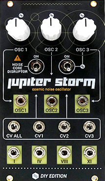
This module can really crank out some crazy noise and random outer‑space sound effects
This is one of the more interesting noise generators I own and it's definitely a keeper. There are some extremely unique sound effects you can achieve once you start toying with the outputs on the I, IV, VIII and XI Noise Channels. The IC's and other components were inexpensive and easy to source. All IC's are priced less than 50¢ each. Note that for best results, the designer recommends using only Texas Instruments brand IC's for IC2, IC4, IC6, IC7 and IC8. Also, be aware that no additional parts are included for mounting the PCB onto the panel. You're on your own
There is an additional 2x5 pin header on the back marked "XPAND". This is used to connect another Hexinverter module called Galilean Moons
- From the Galilean Moons User Manual
- "...the XPAND connector activates the XOR noise output on Galilean Moons and normalizes some of Jupiter Storm’s noise outputs to the VCA inputs of the Galilean Moons module. This arrangement forms a rather powerful synthesis engine with minimal external patching. One of the primary features enabled by expanding a Jupiter Storm is the activation of the XOR noise output seen in the center of the panel jacks on Galilean Moons. This audio output is a harsh XOR gate feedback noise source that can be used to synthesize all manners of unique sounds. The frequency and tone of this noise is determined by Jupiter Storm’s three oscillator frequencies, just like the other outputs on Jupiter Storm. Use it like you would a waveform output from a VCO in your system! Plug it into VCAs, VCFs and otherwise."
The through hole build and off‑board wiring was very easy except for a few annoying hurdles with my Version 1.1 PCB:
- Mounting the crazy oversized PCB onto the panel is an all‑afternoon event. If mounted to the panel at a right angle, the depth measures 90mm (about 3 1/2 inches) and it's impossible to fit into some Eurorack cases which are enclosed (ones with a backplate like the PGH Case[90]). I ended up following some suggestions at a Mod Wiggler thread and used some sheet metal bent at right angles to mount it parallel to the panel. However, this still presents a major issue because it overlaps each side of the panel by 11mm (about 1/2 inch). The PCB is much wider than the panel. I'm only able to install it into my case as long as there is a blank space on either side of it or if it is installed next to modules on both sides which have a lot of clearance (however, no modules like that exist in my rack)
- Standard sized SPDT mini toggle switches will not fit into the panel holes. I had to drill the panel holes slightly larger before a Tayda SKU: A‑4567 would fit
Despite the many hassles needed to mount the PCB onto the panel and then make it fit into a standard Eurorack case, I highly recommend this DIY module. During the mounting and installation phase you will absolutely be cursing it the entire time but hey... I think all modules receive threats and curses during a build. This one will get a double dose of four‑letters thrown at it
Panel/PCB Build Notes & Review
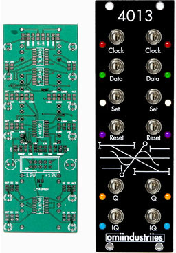
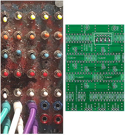
I had one professor during my Electrical Engineering studies who spent three weeks of a Digital Microcircuits course explaining the logic of JK Flip‑Flops. After three weeks, the only person in the class who really understood how it worked was the professor! I feel like I'm back in school trying to wrap my head around this one. It's an excellent module for creating random, glitchy behavior. Using it with my Noise Reap VFD+ produces some amazing psychedelic cacophony and SciFi turbulence I've never heard before. This one is a definite keeper!
- I really like the PCB the designer used for this one!!! The solder pads are very large and because of that, it was the easiest SMT module I've built to date. Like all PCB's with four‑point‑cross GROUND pads, you will want to turn up the soldering iron to a higher setting when soldering any GROUND pads
- The holes in the panel for 3mm LED's are better suited for 2mm LED's. If you use 3mm LED's, they will be recessed. Not really a major issue unless you like to have your LED's stick out the front panel. I used Tayda Electronics 3mm super bright LED's and replaced all twelve 4.7K resistors with 10K resistors (Blue/White/UV/Red/Green/Orange). The six different colors make a mesmerizing light‑show when it's a poppin'
- The PCB silkscreen shows values and IC part#'s for easy placement of all components except R1. I had to pause in the middle of soldering and find a schematic to determine that R1 = 47 Ohms
- The part count is small (less than 60 SMT) and all components are priced low, low, low. The most expensive component was the TL074IDR IC at 82¢ each... only three are needed
Panel/PCB Build Notes & Review
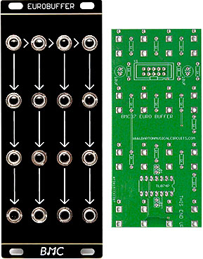
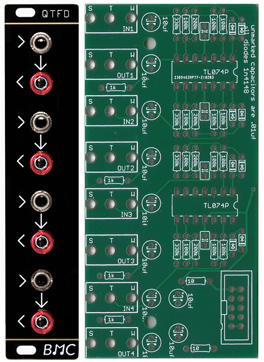
This is a very useful 4‑Channel 1‑to‑3 Buffer. It also allows you to take a single input and replicate its output up to 12 individual jacks or any combination in‑between. Since this is an "Active" buffer, it has the advantage over a "Passive" buffer because there is no signal degradation. The circuit uses a TL074 Op‑Amp wired as a unity buffer. A utility distribution module like this one is a must for any Eurorack setup and I highly recommend this design. It will accept Audio or CV inputs. There are only 35 components to solder in place and one TL074 OpAmp which makes this a quick, easy and very inexpensive build
Currently out of stock at most places but you can always find the PCB at Barton Musical Circuits. The super‑cool noir re‑panel made by Oscillosaurus is usually in stock at ModularAddict.com
Panel/PCB Build Notes & Review
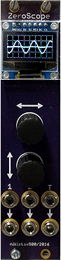
I had this mini‑oscilloscope in my rack for more than a year. It never worked 100% after building it because there was a flat line for all readings less than 100ms. There was also a "T?" error showing at the bottom left of the screen. As suggested by some members at the modwigglers.com Forum, I resoldered R2, R4, D2 and checked for short circuits around the OpAmp. No results
I finally got it working after cleaning the entire board with IPA to remove extremely small amounts of flux in‑between all components which are packed closely together (which is pretty much the entire board). I don't use extra flux for my builds but the flux core in the solder leaves very small traces and was apparently causing random short circuits. I had no idea. This certainly changes the way I will build my modules from now on
Even though this build uses 80% SMD components, I was able to solder everything by hand using a fine tip iron and had no issues (other than the flux problem)
Currently out of stock most places but this PCB/Panel set is sometimes at ModularAddict.com
Panel/PCB Build Notes & Review
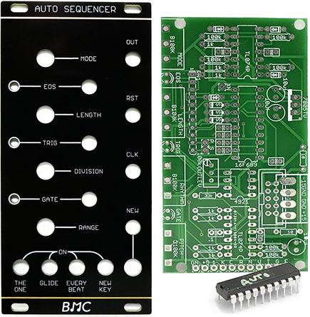
This is a unique step sequencer which programs its own sequences. I find it's very cool for creating percussive sequences on the fly and is great for performing live. It has a CLOCK IN jack to ensure everything is synced up with other modules. There is a selection of controls to help refine the sequences to your own tastes. It has a built‑in quantizer (Major, Minor, Major Pentatonic, Minor Pentatonic, Fifths, Chromatic) and the sequence length range is selectable from 1 to 256 pulses. There is no way of storing and recalling the sequences which it writes... it's an improviser. If you're interested in random composition, or if you're just tired of the hand cramps that come with programming traditional step sequencers, then this is a module you will find useful
The build requires one MCP4921 Digital to Analog Converter IC which is a little pricey at $3 (USD). When you purchase the PCB, a pre‑programmed PIC16F689 FLASH chip is included so you won't need to worry about installing any firmware. All other components are common, low cost and easy to source at Tayda and Mouser
The PCB w/PIC16F689 is always at Barton Musical Circuits and the PCB/PIC16F689/Panel set shows up in‑stock from time to time at ModularAddict.com
Panel/PCB Build Notes & Review
My newest favorite design from Barton is the Toggle Router with 25 sub‑miniature toggle switches. There are plenty of variations for making new sounds with this quick and easy build. It has many uses including a buffer, inverter, mixer and a differential amplifier. My favorite use is manipulating the audio inputs by mixing inverted signals together. When combining different inverted signals, the jumbled mess can produce some amazing sounds. As the designer says, "This module will create sounds you would not get by patching audio inputs normally". I'm having a ton of fun with this new module. There's always something cool to be found at the Barton Musical Circuits website!
All of the components are common and easy to source. The PCB design is carefully mapped out to maximize space for the 25 sub‑miniature toggle switches. The switches are PC pin so soldering is quick and easy and there are no lugs which eliminates a lot of off‑board wiring
The PCB and unfinished, pre‑drilled, raw panel are at Barton Musical Circuits

Panel/PCB Review
I won't dwell on the Random*Source line of DIY modules for very long. My advice is to buy ALL of them because each one is high quality, feature packed and easy to build. This line is slightly more expensive than other DIY modules because a majority of their newer builds have all of the SMT/SMD components pre‑soldered on the PCB's. My favorites are the ÷N COM and Dual Universal Slope Generator

Over the past three years, all sources for PCB/Panel and Full Kits have dried up and evaporated
However, you can still buy assembled modules direct from Random*Source

Panel/PCB Build Notes & Review
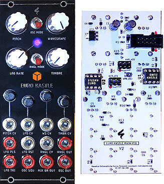
Rich sounds are made possible by using the FM and Sub‑Octave switches which really take advantage of the legendary Curtis Oscillator IC found in the Roland SH‑101, MemoryMoog, Sequential Prophet 5 and Oberheim OB‑Xa. There are also plenty of CV inputs to mangle the sounds (FM, PWM, V/OCT). The Noise toggle switch adds a very nice option to give you that 1970's Synth/Mallet/Percussive combo feel (i.e. "Autobahn" by Kraftwork). I like to set the jumper on the back to "Hard Sync" and feed a complex audio signal into the SYNC input. This can create some interesting "Moog" style sounds. As the main ST‑Modular webpage states, you can get some "very rich sounding analog synth sounds" from this module
This one is a 90% SMD/SMT build. The only through‑hole components on the PCB are the pots, jacks, trimmers, polystyrene capacitor and the custom CEM3340 Curtis VCO IC. Original CEM3340 IC's are difficult to find these days. When you do find them, they can be pricey. A company called Cool Audio makes the equivalent AS3340‑DIL 16‑pin DIP IC for only $6(USD). I used this Cool Audio IC and the sound is phenomenal! This build was slightly challenging for me because I'm lousy at working with those miniature 0603 sized SMD/SMT components. I prefer 0805 sized components instead so it did take longer than my usual builds
Special Assembly Notes:
1) Polystyrene Capacitor - The 1.5nF polystyrene capacitor I used was a Xicon P/N: 23PS215. When soldering this component in place, I recommend using a slightly lower temperature than you normally would. This component is extremely sensitive to heat damage. The soldering temperature should remain below 260º Celsius (500º Fahrenheit) with a touch time limited to a maximum of only three seconds per leg. I always use a heat sink when soldering polystyrene capacitors, thermal fuses and other heat sensitive components. If you don't have one, it's a recommended and inexpensive item to keep in your toolkit. You can find them at Jameco and eBay
2) Calibration - Use a MIDI to CV converter and a tuner, set the Tune and/or Fine pot to reach C, play C1 and C2 alternately and check if it stays on C. Adjust the v/Oct trim pot on the front if it's off a bit. Repeat that for C2 and C3 and so on. Adjust high freq trim if you can't get higher octaves right. Adjust v/offset to reach the correct note. You may also use an oscilloscope or a multimeter in audio frequency mode and using a quantizer in octave mode to adjust frequencies of 100hz, 200hz etc. There are some YouTube videos about the calibration of DIY oscillators. It's always the same basically. Keep in mind to calibrate only after heating the oscillator up for about 20 minutes
Sources are few for this one but PCB/Panel sets are currently at Pusherman
Panel/PCB Build Notes
There are two ATtiny85 IC's which need firmware installed on them
IC U1 = VCO Firmware (KASTLE_VCO_1_5.hex)
The AVR 6‑pin header used for installing this file is labeled AVR_VCO
IC U2 = LFO Firmware (KASTLE_LFO.hex)
The AVR 6‑pin header used for installing this file is labeled AVR_LFO
I have posted a one page firmware installation "CheatSheet" below which is simple and easy to follow. You will need some free software from ATMEL and an AVR Hardware Programmer. Don't panic! This extra gear is not that expensive and you will no doubt get hooked and be using this same programming hardware for future Eurorack builds such as GRIDS, LFOR, BRANCHES & more. I have purchased 20MHz ATtiny85 IC's from Mouser (P/N: 556‑ATTINY85‑20PU) and also from Tayda (SKU: A‑307). Both are working fine with my Euro Kastle modules and I can't tell any difference other than the price. Note that the same firmware files for v1.5 PCB's are also used for the new v2 PCB's
Euro Kastle_V2_BOM.xls Spreadsheet For v2 Build
Both LFO & VCO Firmware *.HEX Files

Euro Kastle v2 Guide
(Click For Larger Image)
(Click For Larger Image)
KASTLE_LFO.hex & KASTLE_VCO_1_5.hex (Available at this link - Firmware.zip)
A couple of things to note about operation:
- The jacks labeled MIX OR OUT and OSC OUT are duplicates. Both will output the same signal
- Formant Synthesis, Phase Distortion and Tonal Noise modes are activated using the upper toggle switch
- This toggle switch alters output for the jack labeled OSC SQU (labeled in red as osc 2 in the "Operation Guide")
Tina Aspiala created a useful operation guide for Euro Kastle v1.5. I have updated the guide and added features for Euro Kastle v2 operation
Euro Kastle v3 PCB/Panel sets are currently at Pusherman
Panel/PCB Build Notes & Review
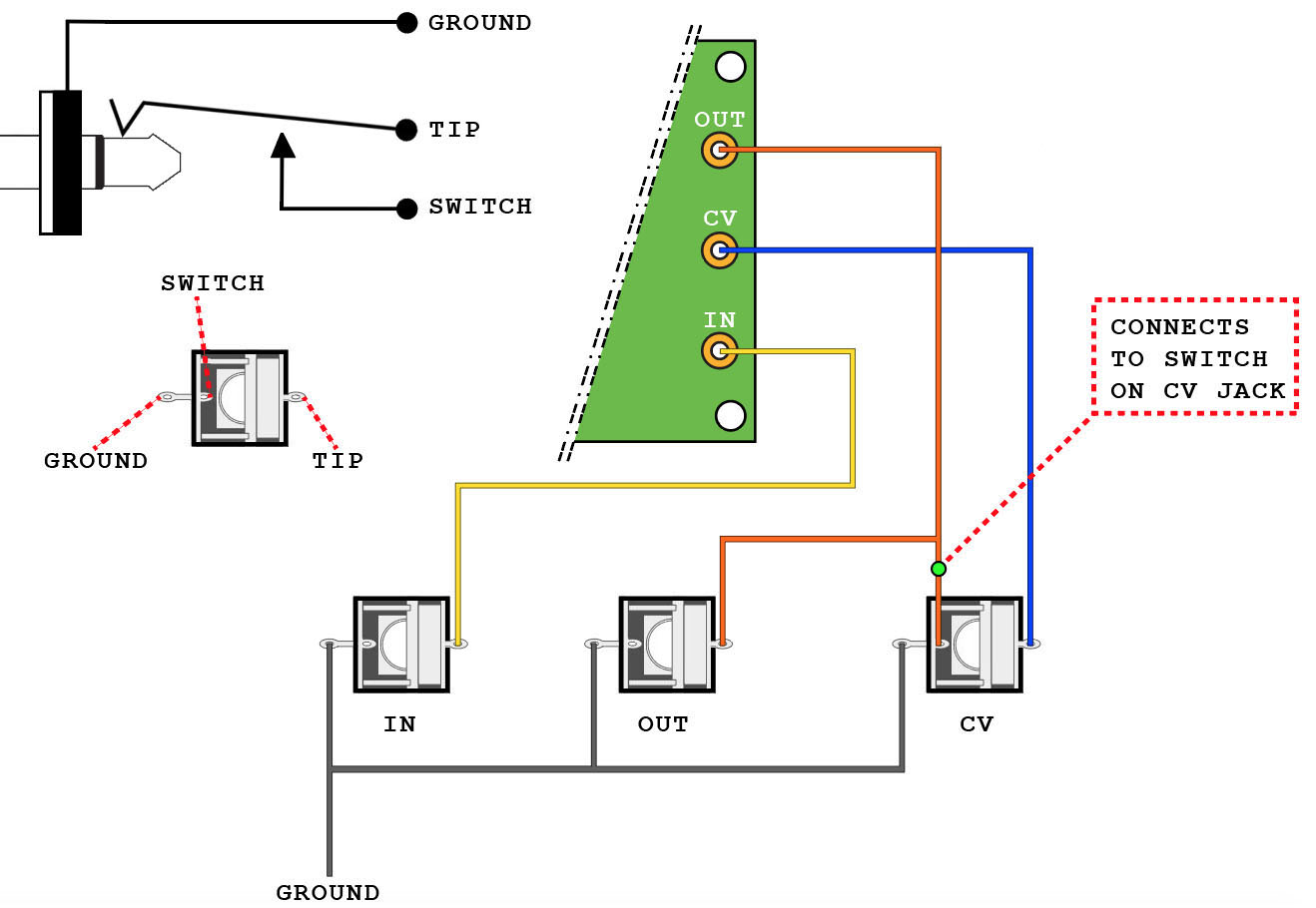
Figure 1
(Click For Larger Image)
(Click For Larger Image)
This module has a myriad of sounds and is one of my favorite "go‑to" modules for percussion. It is a very easy through‑hole build
The build docs do not say much about one of the cool ways to wire it correctly and there are no diagrams showing how. The CV jack can be normalized to the OUT jack for some extra sounds & effects. The TIP lug on the OUT jack connects to OUT on the PCB and also to the SWITCH lug on the CV jack. This effectively turns the CV attenuator knob into a self‑frequency modulation control and adds interesting sounds & effects when no cable is plugged into the CV jack. The image in the build docs for the wiring is somewhat misleading. The OUT jack is actually shown in the wrong position on the panel as compared to all the panels, builds and demos I've seen on YouTube. The OUT jack always appears on the panel in the middle position but it is shown in the build docs on the bottom so be careful when you are wiring this one
The image in Figure 1 shows proper wiring for how the CV jack is normalized to the OUT jack to achieve the extra sounds & effects
MidiverseTV has a video demo at this link
https://www.youtube.com/watch?v=XvnZWxCotTE
Note: This link skips two minutes of the build process
The PCB is always at Barton Musical Circuits and the PCB/Panel set shows up in‑stock from time to time at ModularAddict.com
PCB Build Notes & Review
This is a Highly Recommended build for producing unique harmonic content. It outputs a waveform with a section in the middle chopped out and has separate controls for the top and bottom edge of the chopped section of the waveform. These sections slightly overlap, so when set that nothing is being chopped, a positive offset instead of a negative offset is added in the middle of the waveform. There are two CV inputs and four pots for creating extra mayhem. This has a small footprint, a low parts count and is a super easy build using inexpensive components
The PCB and pre‑drilled panel is at Barton Musical Circuits
PCB Build Notes & Review
What an amazing sound design in such a small footprint! A very low cost and low parts build. This is another Highly Recommended build for producing unique harmonic content. Lately, I've been using it with the outputs of a Mutable Plaits module for some interesting waveforms. My total investment for the Panel, PCB and all components was less than $24(USD)
The PCB and unfinished, pre‑drilled, raw panel is at Barton Musical Circuits
Panel/PCB Build Notes & Review
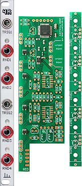
One of my favorite CV generators. An extremely compact quad random voltage generator in only 2HP. It generates two different random stepped voltages per input each time a rising edge is sensed at TRIG1 or TRIG2. The inputs are independent so they can work at different clock speeds. TRIG2 can be normalized to TRIG1 using a jumper pad which makes it possible to get four random values with just one trigger. The voltage range of each output pair can be set as unipolar (0V to +5V) or bipolar (‑5V to +5V) by using jumper blocks on back of the PCB. You can set these jumpers so that two outputs are unipolar and two outputs are bipolar or make all four outputs the same. I have all the jumpers on mine set to bipolar so it will output the widest range of CV signals. This is an excellent companion for use with the Radio Music module. When the jumpers are set to unipolar and the output is connected to the START CV input of Radio Music, the random 0V to +5V signals do a perfect job of selecting a broad range of WAV sample playbacks
There are only three SMD components you need to solder and the rest are all through hole (there are another twelve SMD components with small footprints but these have been pre‑soldered in place at the factory). This one is a very easy build. All components are inexpensive and easy to source. The exception would be the four oddball 24.9K resistors. I'm just guessing that you don't have this value in your parts kit
When this was first released back in 2019, I was lucky to find a new PCB/Panel set for only $29(USD)!!! Unfortunately, the only ones to be found these days are pre‑assembled modules for $110(USD). PCB/Panel sets were available for a very short time at the Pusherman website. You can check the Transient Modules website for other vendors who will (hopefully) restock this PCB/Panel DIY set someday
October 2022 Update: Pusherman has recently re‑stocked this PCB/Panel DIY set. The price has increased slightly to $33(USD) because this is a new Version 2 PCB but... it's still a bargain for this versatile build. So far, the only major difference I can see is a new Calibration SMD pad which is used to set the LED brightness at optimum levels. Get the new Version 2 PCB/Panel set while it lasts here
Panel/PCB Build Notes & Review
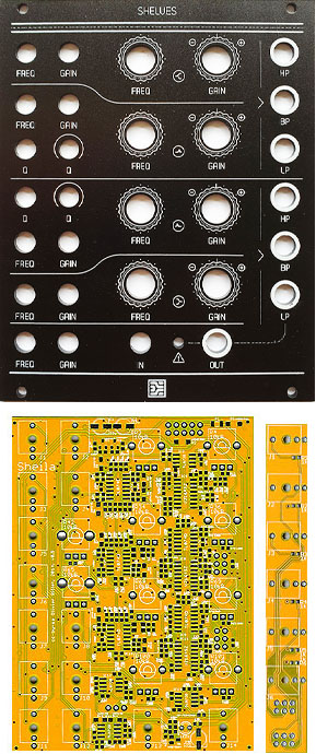
If this PCB/Panel set is buried deep down in your build queue... do yourself a favor and move it near the top right now!
I should never have waited so long to build my Shelves. It was last in my build queue forever because the description of a "4‑Band Parametric EQ" never really appealed to me. It sounded boring. I figured if I wanted to have any EQ that it would be added downstream in the mixing phase. Holy Cow... was I ever wrong. This module is extremely versatile! The sonic palette is vast. There are no STM IC's and there is no firmware to install so it's a very straightforward build. However, there are several SMD IC's which can be intimidating because of their small footprints. Some 0603 SMD soldering skills are definitely required. The PCB is quite crowded and I found myself taking several breaks and spaced things out over two days
Two things to make note of when ordering components are
- There are sixty‑three 100K Ohm metal film resistors and the specs for these require a tolerance of 0.1%. Not 1% like most other builds. This bumps up the build price considerably
- There are some oddball IC's you won't find at Mouser, DigiKey or other big‑name suppliers. Three CoolAudio V2164M Quad VCA SOIC‑16 IC's are needed and you can find them at CabinTech Global for a good price with quick, low‑cost shipping
Pusherman has two high‑quality panels to choose from. Be aware that panels I've seen from other vendors do not have the six extra Bandpass OUT jacks to accommodate the extra Expander PCB
Black Anodized Aluminum Panel
Pusherman Glossy Black Panel
PCB + Expander PCB
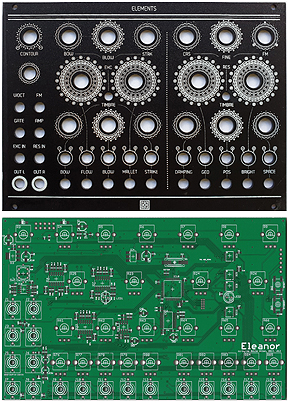
Panel/PCB Build Notes & Review
This is another one I should never have waited so long to build. This is a very large module at 34HP and takes a very L_ O_ N_ G_ time to solder everything in place. There are six SMD IC's with very fine pitch so this one is recommended only for those possessing advanced soldering skills. When installing the firmware on the STM IC, you can use my "CheatSheet" below. With a lengthy component list, this module is a little on the expensive side but... the PCB/Panel set available from Pusherman is quite inexpensive at only $27(USD). The black anodized panel from Antumbra is low priced and has a classy look. The shiny black panel from Magpie Modular is expensive but damn... it looks spectacular!
I was impressed with the sonic landscapes this module offers. It's an excellent tool for re‑creating those mystical Tangerine Dream and ambient‑style sounds from the 1970's/1980's era. The price of a brand new Elements was $550 and you can find pre‑owned modules in the $350 to $450 range. It's still a popular module and has a high resell value
Black Anodized Aluminum Panel (Pusherman)
Black -or- White Panels (Magpie Modular)
Mutated PCB "Eleanor" (Pusherman)
Mutated PCB "Eleanor" (Modular Addict)
STM32 ST-Link Utility (STW-Link004) (Windows Software)
elements_bootloader.hex (Elements Bootloader Download)
elements.hex (Elements Firmware Download)
Panel/PCB Build Notes & Review
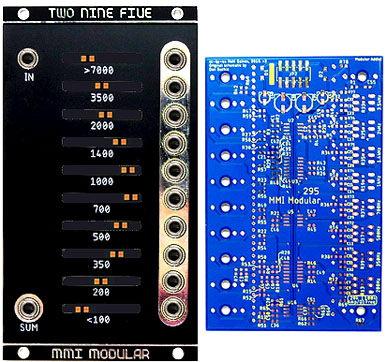
This is an adaptation of the Buchla Model 295 10‑Channel Comb Filter
Looks are deceiving. At first glance it looks like an ordinary Equalizer but it's much more than that. This Comb Filter adds a delayed version of a signal to itself causing constructive and destructive interference. The crazy sound filtering you can get out of this module is impressive!
- About 90% of all components are 0603 SMT/SMD so it takes longer than a through‑hole build. It is absolutely imperative that you solder R13, R39, R17, R37, R19, R35, R25, and R33 in place before mounting the trimpots as they will be very difficult to reach once all components are in place
- There are eight trimpots on the back which allow individual tuning of each Band Frequency, Q's, and Amplitude. Mouser was out of stock of the red sliders at the time of my build so I opted to go with orange and it looks great sporting the 10 LED sliders. This Bourns slider pot is available in three colors
Red: (P/N: 652-PTL20-10R0-103B2) Green: (P/N: 652-PTL20-10G0-103B2) Orange: (P/N: 652-PTL20-10O0-103B2) - If you purchased the Modular Addict v3 PCB (text in the upper right corner of the PCB says Modular Addict) you will notice there are no markings to show correct orientation of the diodes (D1, D2) and the IC's (U1 thru U5). You can view the correct orientations for the v3 PCB using this PCB image or reference the PCB image shown at the MMI Modular Github webpage
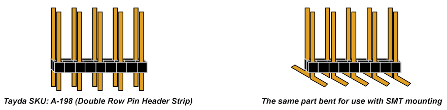
- The BOM shows a pricey SMT 10‑Pin Power Header. I'm notorious for being a cheapskate so whenever possible, I try to use inexpensive parts at hand and modify. I took a 20¢ Double Row Pin Header and used small needle‑nose pliers and bent the pins at opposite right angles. It worked great but soldering that part was a slight challenge because of the tight quarters. Even if you use the expensive part, this component will be a tricky soldering job
You can listen to some Two Nine Five demos here
MMI Modular Webpage
The PCB/Panel set is at Pusherman and also ModularAddict.com
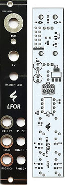
Panel/PCB Build Notes
This is a module in my setup which gets a LOT of use. After using it for several songs, I found it was so versatile that I ended up buying two more. It is very compact at only 4HP but offers many features for such a small module. It sends out three voltages in Pulse, Triangle and Random shapes. It generates random patterns and random triggers and it's easy to manipulate using the three CV inputs of RATE, RESET & RANDOM. The Random Lock toggle switch adds a nice touch for creating repetitive random patterns. An oxymoron? Not really!
This build was inexpensive and extremely easy with a very low parts count. I paid less than $35(USD) for the PCB, Panel and all components. Some of the components are very small 0603 SMD sized so it's recommended that you have some basic SMD soldering skills before attempting this build
The PCB has an EEPROM IC on‑board which needs to have firmware installed but this is a fairly simple procedure. I was completely unfamiliar with installing firmware on a Eurorack module but figured it out right away. I have posted a one page instruction "CheatSheet" below which is simple and easy to follow. You will need some free software from ATMEL and an AVR Hardware Programmer. Don't panic! This extra gear is not that expensive and you will no doubt get hooked and be using this same programming hardware for future Eurorack builds such as GRIDS, EURO KASTLE, BRANCHES & more
BOM + Firmware (i.e. LFOR_BOM.xls and Firmware.zip)
Mouser Cart
SPECIAL NOTE: The Mouser Cart does not include these parts which you can source from taydaelectronics.com or eBay
(Quan: 6) Tayda SKU: A-2563 - PJ-3001F 3.5mm Mono Phone Jack
(Quan: 1) Tayda SKU: A-1848 - 100K Ohm Linear Taper Potentiometer Round Shaft 9mm
(Quan: 1) Tayda SKU: A-1851 - 100K Ohm Linear Taper Potentiometer Knurled Plastic Shaft 9mm
(Quan: 1) Tayda SKU: A-4564 - Knob - Your Choice. I recommend one with a set‑screw such as the Davies 1900H
(Quan: 1) Tayda SKU: A-5290 - Sub‑Mini Toggle Switch ON/OFF/ON
(Note: Pin spacing for this switch is 2.54mm... much smaller than a normal mini‑toggle switch)
The PCB/Panel set is at Pusherman
Firmware Installation - Version 5 Mutated Plateaus 0603 PCB
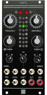
Installing the firmware on this module was quite different from others builds I have encountered. All of my other builds use a standard JTAG 6‑pin header or AVR ISP 6‑pin header to install the firmware. The Plaits PCB uses an SWD 4‑pin header. WTF?!? I was quite confused! It turns out the solution was much easier than anticipated. I was able to use my existing STM32 ST‑Link hardware programmer and a few jumper cables. In fact, this turned out to be one of my easiest firmware installs to date. My cheatsheet and wiring diagrams worked perfectly with the Modular Addict Version 5 Mutated Plateaus 0603 PCB. The same procedures should also work with the Pusherman and the Antumbra KNIT 0603 PCB's however, I have not tested those myself
Not counting the Elements module, Plaits is my favorite design from Mutable. Just like its predecessor Braids, the choice of sonics covers everything from simple sine waves to complex L/R percussive sounds and everything in‑between. Unlike Braids, the extra CV inputs and mini‑pots add a variety of user control. If you want some strange and bizarre sounds, this module is an excellent choice
Firmware HEX File Downloads
Note: Although I really love this Plaits module and all of its amazing sounds and features, I can't say that I was thrilled while assembling this PCB. It was EXTREMELY difficult to solder IC4 in place (STM32F373CCT6). The next time I work with an STM32F373CCT6 IC, a USB microscope will be involved!!! Also, it was very difficult to determine where to place some of the resistors and capacitors. The silkscreen markings are quite ambiguous on the black Modular Addict PCB because there are no parallel lines to show component placement. The green Pusherman PCB is a little better but I still had to reference the *.BRD file from EAGLE CAD to determine which solder pads to use. I created my own high resolution B&W Resistor & Capacitor Placement Sheet from the *.BRD file. Print it and use when soldering components in place
The Mutated Plateaus 0603 PCB and matching anodized black aluminum Panel are at Pusherman
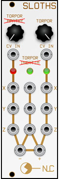
Modification: Changing It To A TORPOR x3 Module
The standard Sloths module has three separate Sloth Chaos circuits and each one runs at a different rate
| TORPOR: | 15‑30 Seconds |
| APATHY: | 60‑90 Seconds |
| INERTIA: | 30‑40 Minutes |
My style of music can't wait 30-40 minutes so I decided to turn my Triple Sloth module into three TORPORS. The modification is very easy by simply changing one potentiometer and some resistor and capacitor values. With help from Andrew at Nonlinear Circuits and member PnP Modular in the Nonlinearcircuits Builders Guild on Facebook, I have compiled a spreadsheet with the new quantities, component values and my build notes
Sloths BOM Modification for Torpor x3
The PCB/Panel set is at Nonlinear Circuits
Panel/PCB Build Notes & Review
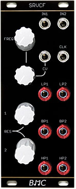
This is one of my favorite filters. The module has two state‑variable filter sections which share a common frequency control and can be used in series for heavier filtering or in parallel to work with stereo sound sources. The Synth DIY Guy YouTube channel has a nice overview of module operation in this video. There are some MP3 examples in the BOM & Build Guide. There are also two videos on YouTube which show normal operation and an interesting mode showing how it is able to create formant vowel sounds
This was a very easy build and with the exception of a solitary DG202 Quad Analog Switch IC, all of the components are common and inexpensive. Most vendors sell the DG202 at overinflated prices in the $13(USD) to $16(USD) price range. Don't let those vultures rip you off! Use the lowest cost DG202 from Mouser which is only $3(USD) (Mouser P/N: 781‑DG202BDJ‑E3). My total build cost for the PCB, Panel and all components was under $47(USD). You can't go wrong with this module. Heck... the cost of the PCB is only $8(USD) so if you don't need the fancy looking Oscillosaurus panel, that drops the total parts cost down to only $27(USD)
Special Build Info: If for some reason you end up with an older v1.0 PCB, note in the BOM & Build Guide that you will need to perform a simple mod by running a jumper wire from a capacitor to the FMOD potentiometer
Update: August 2022
The designer has an updated PCB for this project which improves response when using an external clock input. If you have already built this module using an older v1.0 PCB, I have created a PDF with images which shows how to easily update your v1.0 PCB to v1.1 specs by simply removing some resistors and adding some new ones
BMC034 PCB v1.0 Modified To v1.1 Specs.pdf
The PCB is always at Barton Musical Circuits and the PCB/Panel set shows up in‑stock from time to time at ModularAddict.com

Errors When Installing Firmware
I was unable to use the fancy commercial program ATMEL STUDIO to install firmware on my CVpal and the ATTINY84A EEPROM. I kept getting errors when trying to use the Mutable Instruments recommended settings for the Fuses and Lock Bits
EFuse: 0xFF HFuse:0xD6 LFuse: 0xDE Lock Bit: 0x2F
I eventually gave up trying to use ATMEL STUDIO and finally succeeded by using the command line program called avrdude
Here are my notes showing how I finally made everything work
CVpal Firmware Installation Notes
The PCB/Panel set is at Pusherman
Installing Firmware - Version 3 Mutated "Chloe" PCB
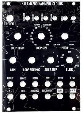
There's not much to say about this one. Basically, if you have a Eurorack skiff, this is a required module. Everyone needs to have a Clouds. The alternative Kammerl Beat‑Repeat firmware enables real‑time slicing, looping and a Spectral Clouds effect (a high‑resolution, auto‑modulated multi‑band filter). When sending audio to the inputs, "It slices, it dices, it makes julienne fries". It's really something special. The original three modes of the official Clouds firmware are still present and have not been modified. This is a highly recommended firmware upgrade. Also, North Coast Modular Collective offers an amazing re‑panel (in white or black versions) which match up with the firmware features for all of the new knob and button selections
Kammerl Beat-Repeat/Spectral Alternative Firmware
Notes About Installing Kammerl From My Experiences:
- When I installed the Kammerl firmware on a brand new fresh build, I had to first install the original
Clouds Bootloader and Clouds *.HEX files (see the "Cheatsheet" above) and then install the Kammerl firmware
- I had an issue the first time I used Kammerl. The Pitch was always stuck at the lowest possible setting. I was never able to set things back to the default using any of the buttons. The only way I was able to correct things was to erase the STM chip and reload the firmware using the sequence below (This was not an issue with the Kammerl firmware but instead was most likely a mistake I made due to my inexperience with using it for the first time. I probably changed and saved some parameters I shouldn't have)
- Run the STM32 ST‑LINK Utility
- From the dropdown menu
- Target Connect >> Program & Verify... >> Install clouds_bootloader.hex
- (See the "Cheatsheet" above for the steps used to install firmware)
- Target Connect >> Program & Verify... >> Install clouds_bootloader.hex
- From the dropdown menu
- Target Connect >> Erase Chip
- Program & Verify...
- Install clouds_bootloader.hex
- Install clouds.hex
- Install clouds_kammerl_firmware_v042.hex
- From the dropdown menu
Here are some informative YouTube videos showcasing the Kammerl Beat-Repeat firmware:
Kammerl Beat-Repeat Tutorial by Voltage Control Lab (External Link) Kammerl Beat-Repeat Demo by DJ Peeb (External Link)
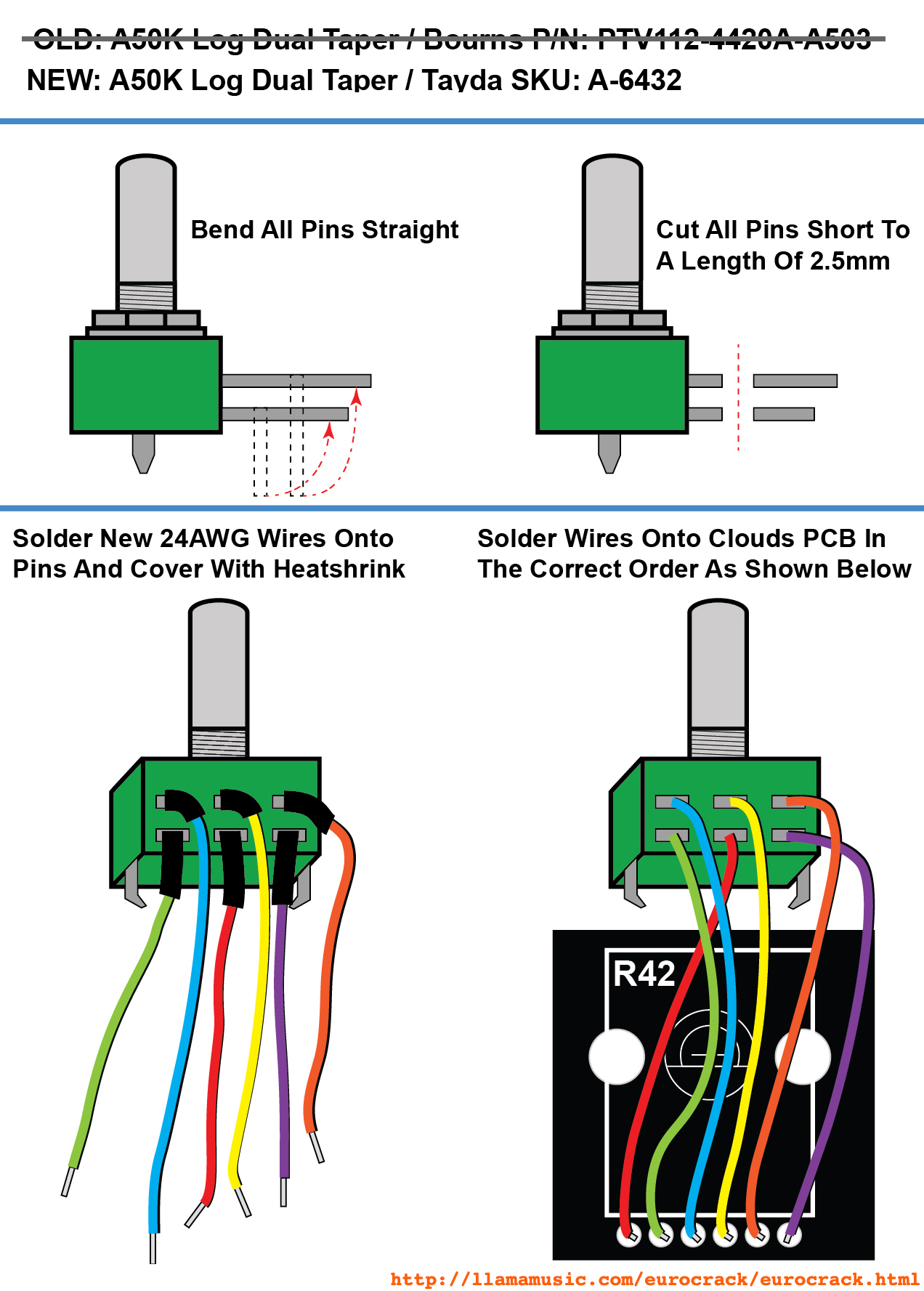
Bonus Info: The original BOM for Clouds uses a crappy plastic dual pot for the GAIN knob. That one wobbles and totally sucks. I can't stand using plastic pots so I replaced mine with a metal pot and rewired it for durability and a better experience. It takes some maneuvering to loop the new wires and place them in the trace holes but I am very satisfied with the results. A wiring diagram and replacement part number is shown in this image
PCB's and Panels at Modular Addict, Magpie Modular, Pusherman and North Coast Modular Collective
Panel/PCB Build Notes & Review
From the Mutable Instruments website --
-
"Your drum section will never be the same again...
Take the user interface of an euclidean sequencer, a healthy dose of machine learning and graph algorithms, megabytes of drum loops, hours of intensive computations and you've got a drum pattern generator like no other
Grids' "brain" is a map of the typical drum patterns used in (mostly electronic) music, laid out by similarity, trained on a large corpus of drum loops. The module can smoothly interpolate and navigate from one pattern to the other, at the whim of a knob move or a CV
But Grids' knowledge of drum patterns goes far beyond what would be achieved with presets – given a position in the map, thousands of variations can be intuitively generated by controlling the "event density" of each of the 3 channels (bd, sd, hh) – gradually moving from a sparse backbone to a deliciously rich pattern with ghost notes, rolls and fills. ... especially when modulated by a noise source!
Add CV-control on these parameters and you can add subtle or drastic variations to the drum pattern. If you don't want to waste a noise source or Sample & Hold for that, Grids has its own internal source of randomness that can unpredictably spice the pattern, in an always meaningful way
Building the rhythmic foundation of your tracks with Grids is fun, surprisingly intuitive, with modulation and variations possibilities that will rapidly make you forget x0x-style sequencers"
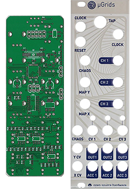
I found the µGrids Programming Guide by Casey Jones PDF was essential for a quality uGrids build. For me, these firmware installation tips were essential and I've used this same guide as an outline for some of my other Mutated/Mutable firmware installs
µGrids Programming Guide by Casey Jones
Individual PCB's and Panels plus PCB/Panel sets are at Pusherman and custom high quality Panels are at MagpieModular.com
A High Quality 420HP Case
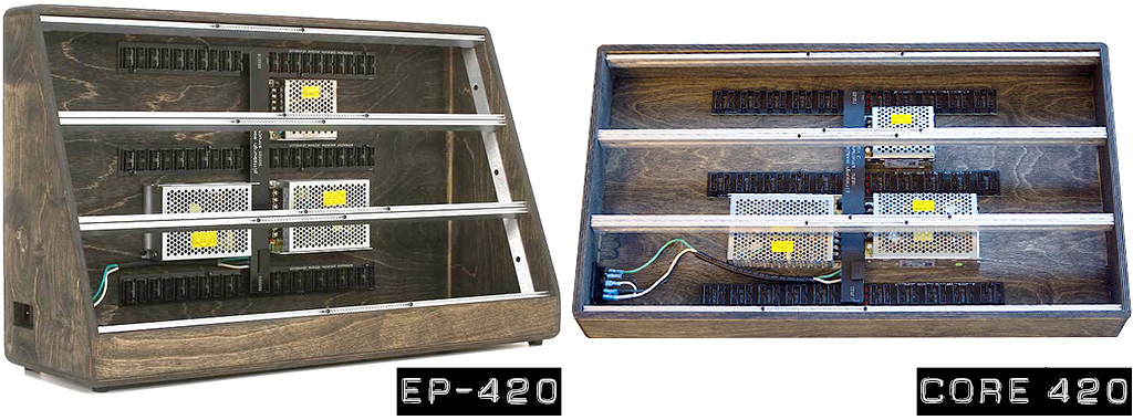
This isn't a DIY build but I'm adding it here because it deserves a special recommendation. It's a monster sized case with a combined 17 Amps of clean, quiet power. Dollar for dollar, I think this case has the most economical price per HP on the market today plus, it has plenty of space for future expansion with 60 keyed ribbon cable headers. I'm very impressed with this solidly built behemoth. The bottom row is extremely deep at 152mm (6 inches) which is great for all of those long, oversized modules (Elby Designs, Doepfer, etc...). I found it was quite easy to remove the default square nuts and add my own (I prefer working with M2.5). Simply remove 6 screws and the entire 420HP vector rail assembly slides out as one solid piece for easy access. Pittsburgh Modular continuously makes innovative and high quality Eurorack gear. Detailed info is at Pittsburgh Modular
This one is selling out fast but Sweetwater still has a few left as of April 2024 with Free Shipping and a Free Extended 2‑Year Warranty!
UPDATE JANUARY 2024
Just when I thought it couldn't get any better... Pittsburgh Modular has released the Structure Core 420 add‑on case for the EP‑420. This companion piece adds an additional 420HP of skyscraper room on top of an existing EP‑420 case. Just like the EP‑420, the Core 420 has EMI filtering, 60 keyed power headers, fuse protection and output overload protection with auto‑recovery. The optional Mounting Bracket Kit is a must so don't forget to buy this from the PGH website. I've been trying to get Sweetwater to stock the mounting bracket kit but so far no luck. However, they do stock the Structure Core 420 which is a big relief because I always want that Free Shipping and Free Extended 2‑Year Warranty!
Bonus
I put together a webpage with some installation tips for attaching a Structure Core 420 on top of an EP‑420 here
Some Eurorack Case Cost Comparisons (Sorted By Total HP Size)
====================  ===  =======  =============  =================================  ==============================================
MAKE/MODEL            HP   COST/HP  DEPTH          PROS                               CONS
====================  ===  =======  =============  =================================  ==============================================
Doepfer A-100PMS12    672    $2.73  Fixed @ 4.01"  Sturdy Travel-Ready Shell / Deep   Very Heavy @45 lbs. & Very Difficult To Move
PGH EP-420 (Black)    420    $2.86  3.49" - 5.89"  Thick Baltic Birch / Very Deep     Heavy & Difficult To Move When Filled
PGH Core 420 (Black)  420    $2.38  1.37" - 2.93"  Thick Baltic Birch / Deep          Not Portable If Attached To EP-420
PGH Core 420 (Plain)  420    $2.15  1.37" - 2.93"  Thick Baltic Birch / Deep          Not Portable If Attached To EP-420 / Unstained
Doepfer A-100LC9      252    $1.86  Fixed @ 4.29"  Low Price / Very Deep              Very Thin Wood Shell / Unstained Plywood
TipTop Audio Mantis   208    $1.62  1.96" - 2.39"  Very Low Price / Moderately Deep   External PSU / Plastic Shell
Intelligel Case-7U    208    $3.37  Fixed @ 2.69"  Extra 1U Module Row / Audio Jacks  External PSU / Very High Price
Arturia RackBrute 6U  176    $2.04  2.19" - 2.95"  Sturdy Aluminum Shell / Deep       PSU Is A Module & Not Built Into The Case
Make Noise 104 Skiff  104    $2.41  2.01" - 2.56"  Sturdy Aluminum Shell / Deep       External PSU / Shallow Depth
Moog 104 Skiff        104    $2.40  1.73" - 1.88"  Sturdy Aluminum Shell              External PSU / Extremely Shallow Depth
Cre8Audio Nifty Case   84    $2.37  Fixed @ 2.17"  Built-in Converter Connections     External PSU / Build Quality Issues Reported
====================================================================================================================================

Notes: 1) After my 2021 review, production costs for the EP-420 went up an extra $200. The "COST/HP" ratio isn't what it used to be
       2) The "COST/HP" ratio is based on current pricing from February 2024 and does not include any shipping fees or taxes
       3) Some cases are larger than others. To equal an EP-420, you need five Cre8Audio Nifty cases (adds five extra wall warts!)
       4) Pittsburgh Modular cases get my vote for the best overall because of the high quality build, features and price
"Analog Is Important"
Pittsburgh Modular does not make any DIY products but I am placing them here to say that this outfit is my #1 absolute favorite Eurorack brand. They always have innovative and unique designs and are constantly developing new modules. It's always good to have some of their boutique gear in your collection. Their limited editions (usually set at only 200 modules) tend to sell out quickly. These turn into some real classic collector's items with a high resell value
Check back from time to time and you'll find some new stuff at their store page. Be sure to check out their YouTube channel as well which contains a lot of useful Eurorack tips and tricks along with some spacey modular jams
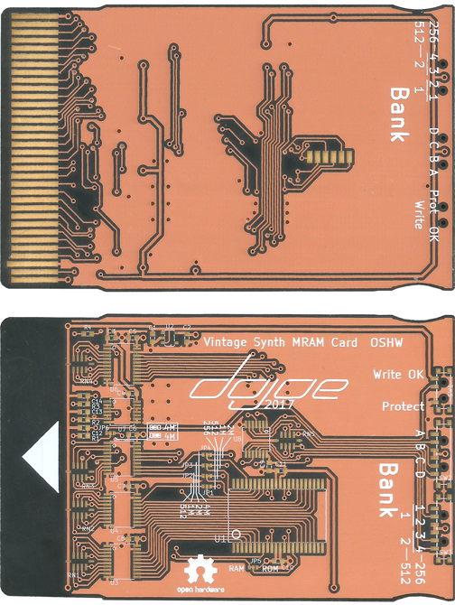
16 Banks Of Patch Data On One Card!
This DIY build is not Eurorack related but it's worth mentioning if you own some vintage Roland synths like the JV‑880, U‑20, GR‑1, D‑10/110, D‑50/550 and others. This amazing custom multi‑bank RAM card is a high quality item designed in Germany. It's the equivalent of having 16 Roland M‑256 RAM cards on one device. It has switches on top so you can easily choose between the 16 individual banks. There's no battery and everything is stored on an MRAM chip. It's possible to mix banks on one card so the ability to move this card between different model synths is convenient and a huge money saver. For the DIY crowd, there are some interesting modifications discussed in the User Manual to emulate PCM ROM cards or increase the bank sizes anywhere from 16 x 256Kbit, 8 x 512Kbit, 4 x 1Mbit, 2 x 2Mbit or 1 x 4Mbit simply by adding some solder bridges. I found the SMD components a little challenging at first (TSOP‑44, TSSOP‑14 and 0603) but after building six of these I was an expert. The designer of this multi‑bank RAM card has released the BOM and schematics into the DIY community for free! KiCAD PCB and Gerber files are at github ‑or‑ you can order PCB's from OSH Park and build your own for half the price of a brand new card. I have built six of these and they are all working great. The total cost including the PCB and all components was less than $55(USD). Purchasing the equivalent amount of 16 Roland M‑256 RAM cards on eBay is about $1,450(USD) so... do the math
 DIY Your Own Multi-Bank RAM Card (External Link)
Multi-Bank RAM Card Info At Saga Musix (External Link)
DIY Your Own Multi-Bank RAM Card (External Link)
Multi-Bank RAM Card Info At Saga Musix (External Link)
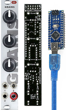
Repair Notes
I was unable to find any detailed documentation about installing the firmware for this module. This was way back in 2018 so I chucked it in a box and decided to work on it later. Two years later I finally got it working after finding a post on Facebook. After reading some posts from others who have never been able to make their module work, I decided to compile my notes which might help them
The main problem I had was with the Arduino Nano board which was bundled in the Full DIY kit. It was un‑configured, blank, broken, brain dead or all of the above and it needed to have a special bootloader reflashed/repaired/installed before it would work. I'm not sure if this is by design of if there was a bad batch of boards from the factory. Just to make sure we don't get confused here, there are actually two Arduino boards being used in this repair process. The Arduino Uno Board which is used to repair the Arduino Nano board and the Arduino Nano board which is part of the actual Grains module assembly
These are the steps I took to finally get my module up and running
- Purchased an Arduino Uno board. The cost is about $10(USD) and looks like the board in Figure 1
- Purchased a Type‑A to Type‑B USB cable. Looks like this and is used with the Uno Board
- Purchased a Type‑A to Mini‑B USB cable. Looks like this and was bundled with my Grains DIY kit
- This is required for installing firmware on the Nano Board
- Purchased a set of Dupont Female to Male jumper wires. Looks like this and are at taydaelectronics.com
- Downloaded the free Arduino IDE software (Mac or Windows ‑ www.arduino.cc/en/main/software)
- This software is needed to Reflash/Repair/Install the bootloader and install firmware into the EEPROM IC on the Nano Board
- This software is needed to Reflash/Repair/Install the bootloader and install firmware into the EEPROM IC on the Nano Board
- Reflashed/Repaired/Installed the bootloader on the Nano Board's EEPROM IC
- Installed Grains firmware on the Nano Board's EEPROM IC via Type‑A to Mini‑B USB cable
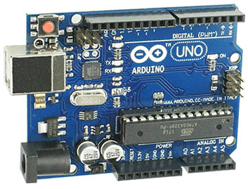
Figure 1
Model# Arduino UNO R3 MEGA328P
Model# Arduino UNO R3 MEGA328P
A broken bootloader on the Nano board is (I think) what some current Grains owners are having issues with. There is a very good video inside the link below which covers the procedure for reflashing/repairing/installing a broken bootloader. Basically, you are connecting wires from the Uno Board to the Nano Board, rebuilding/repairing a new bootloader for the hardware and installing new bootloader EEPROM code. I would recommend skipping the first three steps in the YouTube video and start at Step #4 - Missing Arduino Bootloader
After reflashing/repairing/installing the bootloader (as shown in the video link below), disconnect the Uno board from everything and plug a Type‑A to Mini‑B USB cable from your computer into the Nano Board on the Grains module. Run the Arduino IDE program and upload a new firmware file (there are several to choose from at the GinkoSynthese website)
The settings I used from the Arduino IDE drop‑down menu to load new firmware (these must be done in order)
- Tools ▻ Board ▻ Arduino AVR Boards ▻ Arduino Nano
- Tools ▻ Processor ▻ ATmega328P
- Tools ▻ Port ▻ (Your Serial Port)
- On a Mac it shows up something similar to /dev/cu.usbserial‑1410
- On a PC something similar to COM4
- Tools ▻ Programmer ▻ Arduino as ISP
- File ▻ Open ▻ (Choose a new firmware file. This will be something similar to pwm‑saw‑vca‑vcf.ino)
- This firmware file must have the extension of *.ino
- Sketch ▻ Verify/Compile (returns with the message "Done Compiling")
- Sketch ▻ Upload (Returns with the message "Done Uploading")
- If there are no errors returned, unplug USB cable from the Nano Board, plug the Grains module into your Eurorack case and test the new firmware
Note: If you are working on a Mac, you can probably ignore the section about USB drivers. Unless you are still working on a system with an older O/S, Mojave 10.14 or later (October 2018) already includes a CH34x USB driver by Apple. If both Apple's and the new OEM's drivers are installed, they will create conflicting non‑functional serial ports. If you are unable to select a valid serial port on a Mac or a PC then you may need to install these extra Serial Drivers after all (refer to the video link)
Reflash/Repair/Install Bootloader Instructions (With Video)
Interesting side note: Someone ported Mini Pops firmware code and modified it to work with this Grains module. I have installed it on Grains and it sounds very cool. It's a little harder to manipulate than the original Mini Pops because there are no switches to turn individual instruments On/Off but it does have more advantages of being able to control the instruments, patterns and tempos by CV Inputs and/or Pots. This alternative firmware is at the EMast42 GitHub webpage
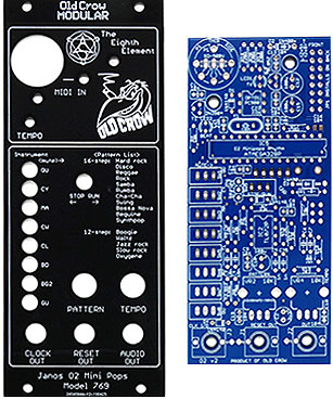
Panel/PCB Build Notes
UPDATE: OCTOBER 2021 - BE ADVISED THAT OLD CROW MODULAR OFFERS ZERO SUPPORT AT ITS WEBSITE FOR THIS MODULE AND WILL NOT RESPOND TO ANY EMAIL REQUESTS. I have confirmed with another builder and he is getting the same terrible muffled and lackluster sound as I am. Something with this module is definitely off. Also, the MIDI input is not non‑functional because there is no code for this feature in the firmware. Bad design, bad firmware. I do not recommend purchasing this module with the firmware that's available and zero support from the designer
If you already have the PCB/Panel, here's the scoop. The original Korg Mini Pops 7 is famous as one of the rhythm machines featured on Jean‑Michel Jarre LP's titled "OXYGENE", "EQUINOXE" and "THE CONCERTS IN CHINA". There is a detailed webpage about the original rhythm machine here
I finally found a copy of the firmware and BOM from a source and was able to build the module. There was no build documentation and no firmware posted online anywhere and I had some requests for info about it from other builders. My build sounds nothing like an original Korg Mini Pops 7. The Audio Out is muffled and unpronounced. Also, the MIDI IN jack does not work and I see nothing in the firmware code to support any type of MIDI IN requests
I have assembled some images and text files with my build docs, bootloader + firmware files, Mouser Cart, BOM and firmware installation instructions using an AVRISP MKII Programmer with Atmel Studio v7 ‑or‑ a TL866CS EPROM Burner with TL866A/CS Application Software. Both are for use on a Windows PC
Abbreviations for instrument sounds on the panel might not be apparent at first glance. They are
   QU = Quijada
   CY = Cymbal
   MA = Maracas
   CW = Cow Bell
   CL = Claves
   BD = Bass Drum
  BG2 = Bongo
   GU = Guiro
I found this build to be extremely challenging because
- There are no schematics, no build documentation and no BOM online for downloading
- The designer (Old Crow Modular) has not answered any of my support eMails for any modules dating all the way back to 2017
- And yes... I was stupid enough to buy it anyway. I do like challenges
All of these files and images will all be placed in one *.ZIP file for easy downloading. Someday. For now, easier for me to update
Bootloader + Firmware + INO
Populated PCB
Original Korg MP-7 Schematic
BOM
Mouser Cart (Note: Nine Toggle Switches Three Mono Jacks, Two Pots & Two Knobs Are Not Included)
SPECIAL NOTE: You can source these parts from taydaelectronics.com
(Quan: 3) SKU: A-2563 - PJ-3001F 3.5mm Mono Phone Jack
(Quan: 2) SKU: A-1847 - 10K Ohm Linear Taper Potentiometer Round Shaft 9mm
Search eBay for the sub-mini toggle switches and knobs
Interesting side note: Someone ported Mini Pops firmware code and modified it to work with the GinkoSynthese Grains module. I have installed it on Grains and it sounds very cool. It's a little harder to manipulate than the original Mini Pops because there are no switches to turn individual instruments On/Off but it does have more advantages of being able to control the instruments, patterns and tempos by CV Inputs and/or Pots. Alternative firmware for Grains is at the EMast42 GitHub webpage
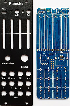
Firmware Installation Notes
I was a noob when I installed the firmware on this module so it wasn't very easy for me starting out from scratch. I have put together an instruction "CheatSheet" which should make installing firmware on this module easy for any beginner
STM32 ST-Link Utility (STW-Link004) (Windows Software)
frames_bootloader.hex (Frames Bootloader Download)
frames.hex (Frames Firmware Download)
The PCB/Panel set is at Pusherman
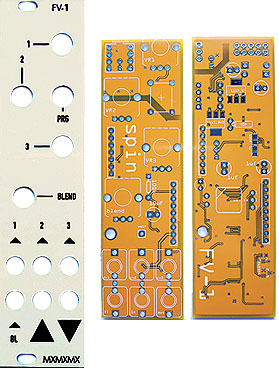
Firmware Installation Notes
The designer of this module has a minimal build guide for this one. What an understatement. This was a very difficult build due to lack of documentation. The BOM is missing some parts and there is virtually zero info re: how to install the firmware for the internal ATtiny85 EEPROM or the external 24LC32A EEPROM. If you like a challenge... buy this PCB/Panel set. You won't be disappointed. I'm posting this here for anyone else struggling to get it working. I've been able to get the eight internal programs on the SPIN FV‑1 ROM working just fine but still have not been able to load any custom code into the external EEPROM. The code I was able to load on the internal EEPROM is very basic. The purpose of this code is to cycle through the eight FX programs contained on the SPIN FV‑1 ROM. I will update this page If/When I figure out how to send custom user code to the external ERPOM someday. It's working as‑is using the PRG button and it can access these eight FX programs
     0 Chorus/Reverb
     1 Flange/Reverb
     2 Tremolo/reverb
     3 Pitch/Shift
     4 Pitch/Echo
     5 Test
     6 Reverb 1
     7 Reverb 2
The input jack labeled BL accepts CV signal inputs and will vary the amount of BLEND between a dry signal and the currently selected FX. The three CV inputs and three potentiometers labeled 1, 2 and 3 are non‑functional at the moment. My guess is these will only work if custom firmware is installed on the external EEPROM. Likewise, the BL CV input currently has no effect on any of the CV inputs 1, 2 or 3
Extra parts needed for this build not shown on the BOM are
(1) 10uH Inductor - Mouser P/N: 810-MLF2012E100JTD25
(1) Tact Switch Cap - Mouser P/N: 642-1SS00-15.0 (this P/N is blue but is also available in green, grey, yellow, white, red or black)
(1) 32.768KHz Crystal - Mouser P/N: 732-C002RX32.76K-EPB
Items needed for installing firmware on the ATtiny85 EEPROM are
- Arduino UNO board. It costs about $10(USD) and looks like the board in Figure 1 (see the Grains module above)
- Type‑A to Type‑B USB cable. Looks like this and is used with the Arduino Uno Board
- Set of Dupont Male to Male jumper wires. Looks like this and is at taydaelectronics.com
- Project Breadboard. Looks like this and is used to program the ATtiny85 IC
- Free Arduino IDE software (Mac or Windows ‑ www.arduino.cc/en/main/software)
- This software is needed to program the ATtiny85 IC
- A one‑liner from the mxmxmx docs says this can also be used to load custom user EEPROM code. So far... no luck
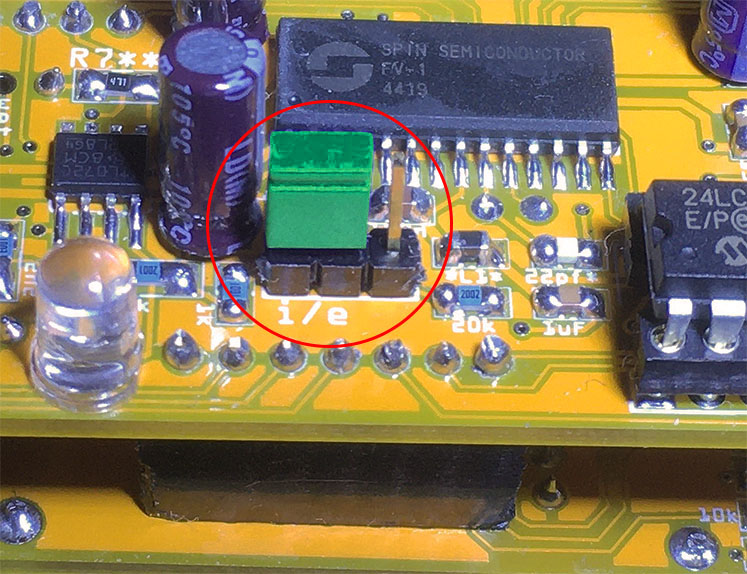
Figure A
Jumper "i" For Internal Patches
(click for larger image)
Jumper "i" For Internal Patches
(click for larger image)
SPECIAL NOTE: Before you can use any of the internal programs in ROM, you will need to set a jumper for the 3‑pin header on the backside of the PCB. This position is shown on the silkscreen as a lower case "i" (See Figure A)
mxmxmx Spin FV-1 Github Page / Build Guide + Firmware
PCB's and Panels at Pusherman
Spin FV-1 Panel
Spin FV-1 PCB
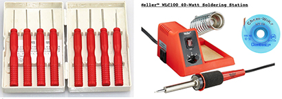
Tips For DIY Freaks Who Like To Save $$$. I picked this selection of gadgets and vendors because of the extremely LOW cost. I use everything shown here almost every day and highly recommend each one
Favorite DIY Tools And DIY Vendors
I think these two topics are important enough to place on all of my synth INFO webpages
1) I buy a lot of broken synths on eBay and I'm able to fix about 90% of everything I find. It's usually a simple fix. If you have a synth with no power or intermittent problems after it warms up, it's probably due to the fact that back in the 1980's Roland and other synth makers used sub‑par solder and/or not enough solder to hold components in place. After 30+ years, the solder begins to break down and hairline fractures appear. This occurs at a higher rate for components which generate a lot of heat like Bridge Rectifiers, Power Transistors, large Electrolytic Capacitors, power input jacks and audio sockets which get a lot of use. The best approach is to use a magnifying glass and carefully inspect the backside of the circuit board. If you spot any suspect areas, re‑flow a hefty amount of NEW solder
These MIDI interfaces have been tested and will work with large SysEx Dumps:
      ✓ Focusrite Scarlett 2i4 2nd Gen    ✓ MOTU 823 mk3               ✓ RME FireFace UC 2X2
      ✓ Focusrite Scarlett 4i4 2nd Gen    ✓ ESI Midimate eX            ✓ M-Audio Profire 2626
      ✓ Focusrite Scarlett 6i6 3rd Gen    ✓ Yamaha UX 16 USB/MIDI      ✓ Tie Studio MIDI 1i1o
      ✓ Miditech MIDIface II Thru         ✓ iConnectivity mioXC 1x1    ✓ Miditech MIDIface 4x4
      ✓ ESI Midimate II                   ✓ iConnectivity mio 1x1
These MIDI interfaces are shit and do not work with large SysEx Dumps (some might w/special driver):
     ✗ AVID/M-Audio Fast Track Pro      ✗ M-Audio MIDISport UNO      ✗ M-Audio MIDISport 1x1
     ✗ M-Audio Uno                      ✗ Lekato MIDI USB            ✗ DigitalLife MIDI-C01
     ✗ Fore MIDI Interface              ✗ Hosa USM-422 MIDI          ✗ M-Audio MIDISport 2X2
     ✗ Hosongnic, HiFangeow, etc...
Safety Precautions
Modifications made to any factory stock equipment will always pose an element of risk. Sometimes mistakes are made which are irreversible. Improper soldering and handling of electricity can cause serious injury and damage the synthesizer. Use caution when handling static sensitive devices and the PCB. Make sure you are properly grounded, working on a static‑free workbench or table and wearing eye protection during any soldering tasks. The author is not responsible for any damage or injury resulting from this DIY info. Use this DIY information at your own risk. And, I can't stress enough, the importance of wearing eye protection while soldering. That stuff flies everywhere sometimes!
Modifications made to any factory stock equipment will always pose an element of risk. Sometimes mistakes are made which are irreversible. Improper soldering and handling of electricity can cause serious injury and damage the synthesizer. Use caution when handling static sensitive devices and the PCB. Make sure you are properly grounded, working on a static‑free workbench or table and wearing eye protection during any soldering tasks. The author is not responsible for any damage or injury resulting from this DIY info. Use this DIY information at your own risk. And, I can't stress enough, the importance of wearing eye protection while soldering. That stuff flies everywhere sometimes!
| If you find some of this DIY info useful, please consider donating a small amount. All donations are used for future DIY synth and sampler development. Thanks! | 
|
Other Synthesizer And Sampler Homepages I Maintain
All images, text, JavaScript and HTML Code ©1995- by llamamusic.com
The Information On This Page Is Current As Of
WEBSITE DISCLAIMER
Last updated October 31, 2014
1) You may not copy, reproduce, republish, disassemble, decompile, reverse engineer, post, make available to the public, or otherwise use the content of this website (including all software applications, scripts, web‑pages, design elements, and graphics) for commercial gain in any way
2) By using the llamamusic.com website and its services you agree to be bound by these terms, which shall take effect immediately on your first use of this website. You may not use llamamusic.com services if you do not accept the terms. If you do not agree to be bound by all of the following terms please do not access and use llamamusic.com. llamamusic.com reserves rights to block violators of these terms from using its services or restrict their access in any form at any time
3) You agree that lawful owners of llamamusic.com own all legal right, title, copyrights, design rights, and other intellectual property rights (registered and unregistered) in this website and all content (including all software applications) located on the site
4) llamamusic.com website content and services are provided "AS IS" and on an "AS AVAILABLE" basis. To the extent permitted by law, llamamusic.com excludes all representations and warranties (whether express or implied by law), including the implied warranties of satisfactory quality, fitness for a particular purpose, non‑infringement, compatibility, security, and accuracy. llamamusic.com does not guarantee the accuracy, completeness, or performance of the website or any of the content and services. While we try to ensure that all functionality provided is correct, no responsibility is accepted by or on behalf of llamamusic.com for any errors or inaccurate content on the website
5) llamamusic.com shall not be liable for any of the following losses or damage (whether such damage or losses were foreseen, foreseeable, known, or otherwise): (a) loss of data; (b) loss of revenue or anticipated profits; (c) loss of business; (d) loss of opportunity; (e) loss of goodwill or injury to reputation; (f) losses suffered by third parties; or (g) any indirect, consequential, special or exemplary damages arising from the use of llamamusic.com and its services regardless of the form of action
6) You agree to use this website only for lawful purposes, and in a way that does not infringe the rights of, restrict or inhibit anyone else’s use of llamamusic.com
7) The information provided by llamamusic.com ("we," "us," or "our") on llamamusic.com (the "Site") is for general informational purposes only. All information on the Site is provided in good faith, however we make no representation or warranty of any kind, express or implied, regarding the accuracy, adequacy, validity, reliability, availability, or completeness of any information on the Site. UNDER NO CIRCUMSTANCE SHALL WE HAVE ANY LIABILITY TO YOU FOR ANY LOSS OR DAMAGE OF ANY KIND INCURRED AS A RESULT OF THE USE OF THE SITE OR RELIANCE ON ANY INFORMATION PROVIDED ON THE SITE. YOUR USE OF THE SITE AND YOUR RELIANCE ON ANY INFORMATION ON THE SITE IS SOLELY AT YOUR OWN RISK
EXTERNAL LINKS DISCLAIMER
The Site may contain (or you may be sent through the Site) links to other websites or content belonging to or originating from third parties or links to websites and features in banners or other advertising. Such external links are not investigated, monitored, or checked for accuracy, adequacy, validity, reliability, availability, or completeness by us. WE DO NOT WARRANT, ENDORSE, GUARANTEE, OR ASSUME RESPONSIBILITY FOR THE ACCURACY OR RELIABILITY OF ANY INFORMATION OFFERED BY THIRD‑PARTY WEBSITES LINKED THROUGH THE SITE OR ANY WEBSITE OR FEATURE LINKED IN ANY BANNER OR OTHER ADVERTISING. WE WILL NOT BE A PARTY TO OR IN ANY WAY BE RESPONSIBLE FOR MONITORING ANY TRANSACTION BETWEEN YOU AND THIRD‑PARTY PROVIDERS OF PRODUCTS OR SERVICES
AFFILIATES DISCLAIMER
The Site may contain links to affiliate websites. Our affiliates include the following:
• supersynthprojects.com • vecoven.com • super-jx.com
